80S20 circuit.pdf - 第95页
4 80S-20/OPTIONS Circu it Diagrams 95 00117185-010101FD4 110/208V conv ersion ki t for SIPLA CE 80 S20 / S23 / F4 / F5 (Sh. 1 of 2) 00117185-010101FD4 110/208V conv ersion ki t for SIPLA CE 80 S20 / S23 / F4 / F5 (Sh. 2 …
4 80S-20/OPTIONS Circuit Diagrams 94
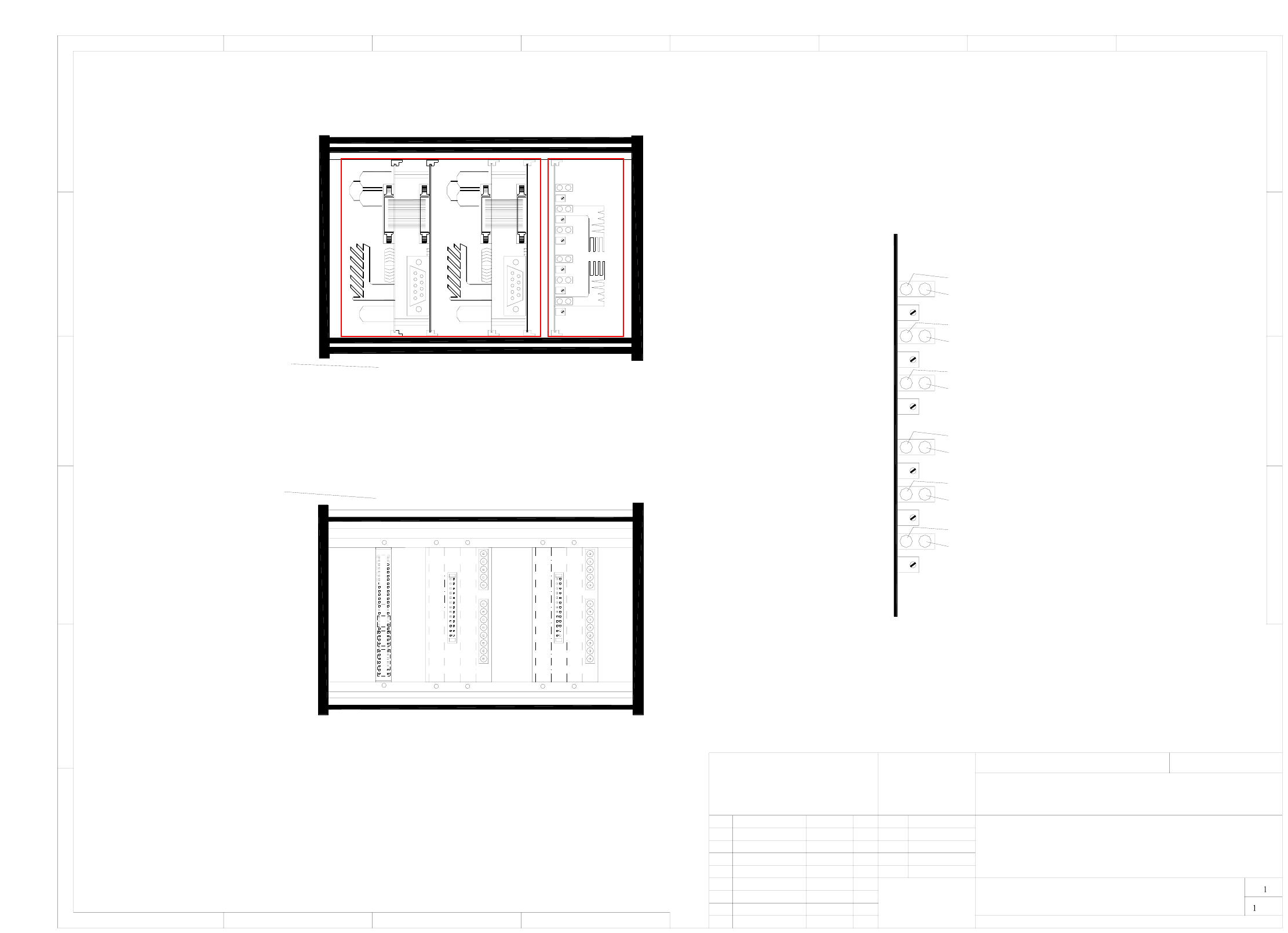
00327615-020101TD3 Control unit, dual conveyor (viewed from the front/back) (assemblies overview)
26 21 17 10 6
Half bridge board
26.06.1996
Dietel
1.
Wer
Wer
2.
14.05.97
14.05.97
1.
14.05.97
Wer
80S20/DCTA/
32761521_d
(assemblies overview)
Input conveyor 2
Output conveyor 2 slow 2
Input conveyor 2 fast
Output conveyor 2
Output conveyor 2 slow 1
X4c X5c X2c
X3c
X3a
X5a
X4a
X3b
X5b
X4b
Half bridge board
Backplane, twin step
motor board, conveyor 1
Backplane, twin step
motor board, conveyor 2
Viewed from the back
module rail hole no.
Board rail in
Viewed from the front
22/2318/1911/12 25/267/8
Twin step motor board, conveyor 2
Twin step motor board, conveyor 1
Output conveyor 2 fast
Center conveyor 2
Center conveyor 2 slow
Center conveyor 2 fast
Center conveyor 1
Center conveyor 1 slow
Center conveyor 1 fast
Output conveyor 1
Output conveyor 1 slow 1
Output conveyor 1 fast
Input conveyor 1
Output conveyor 1 slow 2
Input conveyor 1 fast
Half bridge board
(viewed from the front/back)
Control unit, dual conveyor
00327615-020101TD3
Siemens AG
1
1
243
2345678
A
B
C
D
E
F
A
B
C
D
AUT5-BSM
SMD-Placement System Siplace 80S20
Function status
Doc. status
Product status
Multipole connector / backplane
of module rail.
Mat.-Nr. :
CAD file:
Stat. Modified Date Name
Author
Stand.
Check.
Date
Scale
Sh.
Sh.
in internally threaded hole no.
See page 125
See page 124
4 80S-20/OPTIONS Circuit Diagrams 95
00117185-010101FD4 110/208V conversion kit for SIPLACE 80 S20 / S23 / F4 / F5 (Sh. 1 of 2)
00117185-010101FD4 110/208V conversion kit for SIPLACE 80 S20 / S23 / F4 / F5 (Sh. 2 of 2)
01.
01.
01.
14.01.99
14.01.99
14.01.99 Tek
Tek
Tek
14.01.1999
09.02.99
SMD Placement Systems 80 S20 / S23 / F4 / F5
Conversion kit 110/208V
for SIPLACE 80 S20 / S23 / F4 / F5
00117185-010101FD4
SIEMENS
Aktiengesellschaft
PL EA 1 E2
Date
Author
Check.
Stand.
Name
Filename:
Stat.
Modified
Date
Name
(Drawing number)
Format A4
Drw. no.: FS PS DS S/F
Sheet
Scale
Weitergabe sowie Vervielfältigung dieser Unterlage, Verwertung und Mitteilung ihres
Inhaltes nicht gestattet, soweit nicht ausdrücklich zugestanden. Zuwiderhandlungen
verpflichten zu Schadenersatz. Alle Rechte für den Fall der Patenterteilung oder GM-
Eintragung vorbehalten.
Copying of this document, and giving it to others and the use or communication of the
contents thereof, are forbidden without express authority. Offenders are liable to the
payment of damages. All rights are reserved in the event of the grant of a patent or the
registration of the utility model or design.
Function status
Product status
Document status
(a1_1zu1.vsd)
00117185.vsd
1/2
Berger
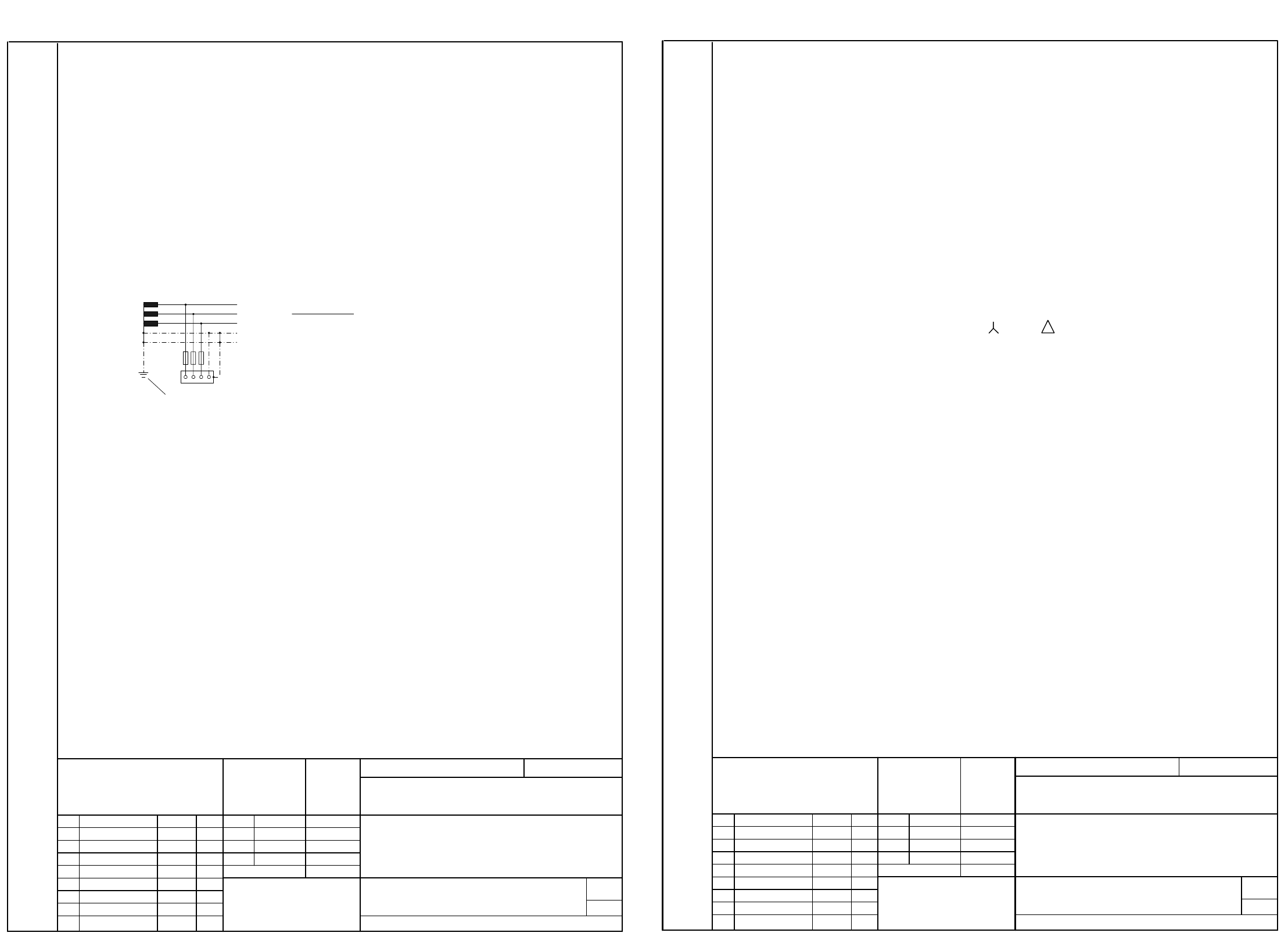
Instructions for converting SIPLACE 80 S20 / S23 / F4 / F5
from 230/400V to 110/208V
a) Terminal panel (right side)
Terminal panel (right side) S20/F4: 00321510
Terminal panel (right side) S23 : 00337342
- BR3/4 jumpers N terminal
↔
PE terminal
Note re BR3/4 :
BR3/4 jumpers should only be used in a 4-wire system.
b) Power supply for S20 / S23 / F4 / F5
Power supply for S20/F4: 00321086
Power supply for S23 : 00336812
- Transformer T1 Pin 6
⇒
Pin 4
- Transformer T2 Pin 1
⇒
Pin 7 ( 400
⇒
208 )
Pin 2
⇒
Pin 8 ( 400
⇒
208 )
Pin 3
⇒
Pin 9 ( 400
⇒
208 )
-Fuse F1 16A
-Fuse F2 16A
-Fuse F3 10A
- Inrush current limiter A1 400V
⇒
230V
From FS05 onwards
(power supply for S20/F4 00321510) and
from FS02 onwards
(power supply for S23 00336812), follow the instructions on the 3rd page of the circuit
diagram when carrying out the conversion:
- Inrush current limiter ESP-S20 A1 400V
⇒
230V
(Material number: 00342988-01 )
TN-C system:
Neutral and protective earth
functions are combined in a
single conductor throughout
the system - the PEN conductor.
L 1
L 2
L 3
N
PE
Grounding of system
01.
01.
01.
14.01.99
14.01.99
14.01.99 Tek
Tek
Tek
14.01.1999
09.02.99
SMD Placement Systems 80 S20 / S23 / F4 / F5
Conversion kit 110/208V
for SIPLACE 80 S20 / S23 / F4 / F5
00117185-010101FD4
SIEMENS
Aktiengesellschaft
PL EA 1 E2
Date
Author
Check.
dp
Name
Filename:
Stat.
Modified
Date
Name
(Drawing number)
Format A4
Drw. no.: FS PS DS S/F
Sheet
Scale
Weitergabe sowie Vervielfältigung dieser Unterlage, Verwertung und Mitteilung ihres
Inhaltes nicht gestattet, soweit nicht ausdrücklich zugestanden. Zuwiderhandlungen
verpflichten zu Schadenersatz. Alle Rechte für den Fall der Patenterteilung oder GM-
Eintragung vorbehalten.
Copying of this document, and giving it to others and the use or communication of the
contents thereof, are forbidden without express authority. Offenders are liable to the
payment of damages. All rights are reserved in the event of the grant of a patent or the
registration of the utility model or design.
Function status
Product status
Document status
(a1_1zu1.vsd)
00117185.vsd
2/2
Berger
a) Service socket 00300272
- Plug-in adapter X1
b) Transformer for component table 00301239
- Transformer T1 Pin 5
⇒
Pin 4
- Fuse F1 3.16AT
⇒
6.30AT
- Adhesive label 6.3AT/110V
c) Power supply for WPC 00320064
- Transformer T1
⇒
4 80S-20/OPTIONS Circuit Diagrams 96
00117185-010101LD3 110/208V conversion kit for SIPLACE 80 S20 / S23 / F4 / F5 (Sh. 1 of 3)
=
Gepr.
Norm
Bearb.
Urspr. Ers. f. Ers. d.Name
SIEMENS AG
+
PEL2 L2
31 7
A
F
C
D
2
L1
E
D
L1
54 6
NL3L3 5PE
3 78
C
B
A
NN
5
F
6
8
1 4
B
Wa
Wa
Tek
01.
01.
01.
14.10.98
14.10.98
14.10.1998
Berger
#
00117185-010101LD3
10.03.99
E
X206
2
PE
PL EA1 E2
3
1
2
gnye
BR3
2,5mm
2
BR4
gnye
Power supply unit (control unit)
2,5mm
2
150V / 60Hz
rd
2,5mm
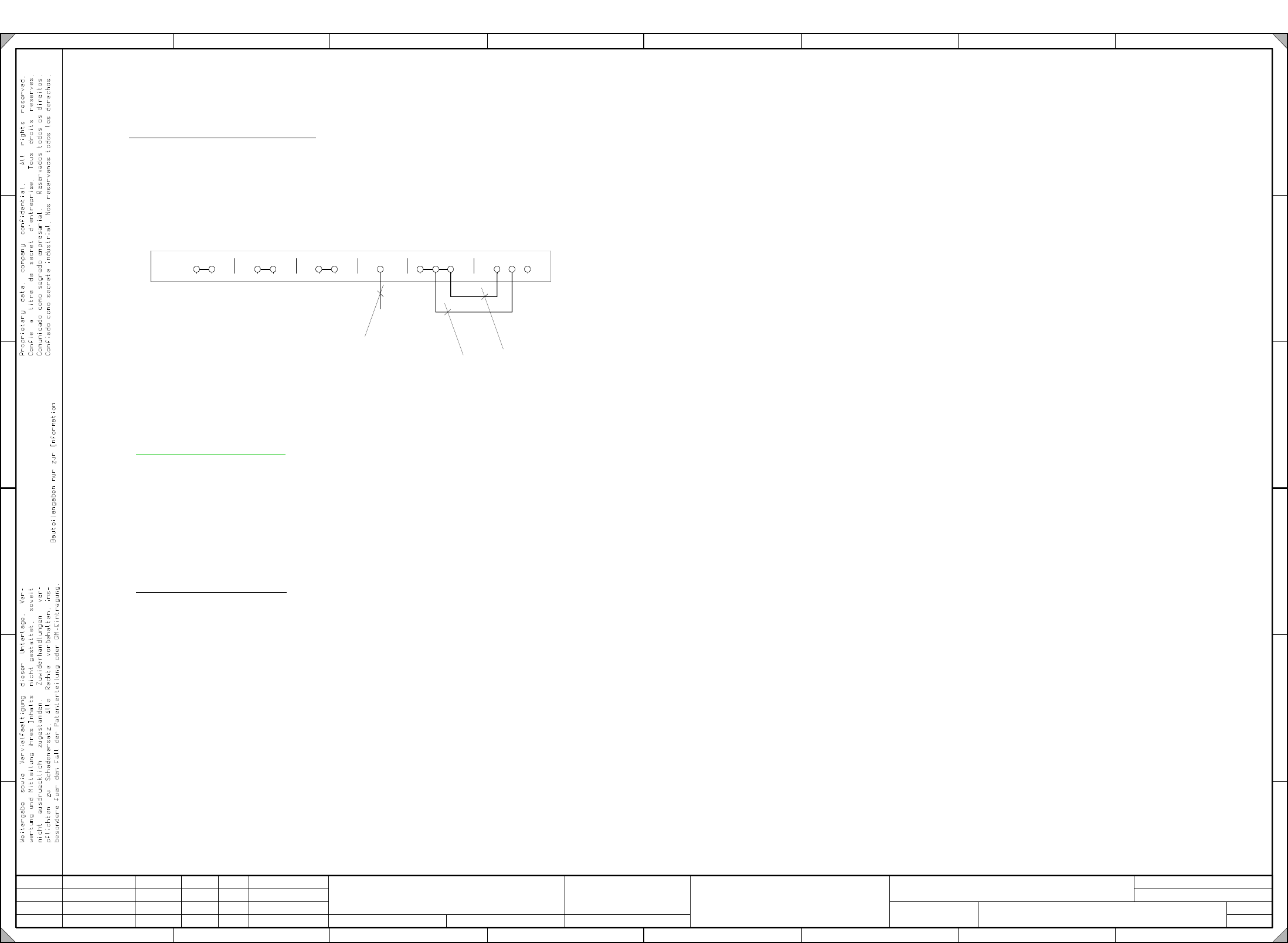
Terminal panel ( right-hand side )
Section a):
Date
Sheet
DateModificationIssue
Sh.
for SIPLACE 80 S20 / S23 / F4 / F5
SIPLACE 80 S20 / S23 / F4 / F5 SMD Placement System
Function status
Product status
Document status
110/208V Conversion Kit
Please note TN-C system
In a four-wire TN-C system, the neutral and PE conductor functions
must be combined in a single conductor the PEN conductor throughout the entire system
(jumpers BR3/BR4).
Please note TN-S system
Jumpers BR3/BR4 must not be used in a five-wire TN-S system.
(The neutral and PE conductors are kept separate throughout the system).