技术资料.pdf - 第11页
11 34980A Multi plexer Switch Modules The 3498 0A multi plexer mo dules c an be used to conne ct one of many d ifferent p oints to a s ingle point. You can c onnect t o an exte rnal inst rument or scan m ultiple a nalog …
10
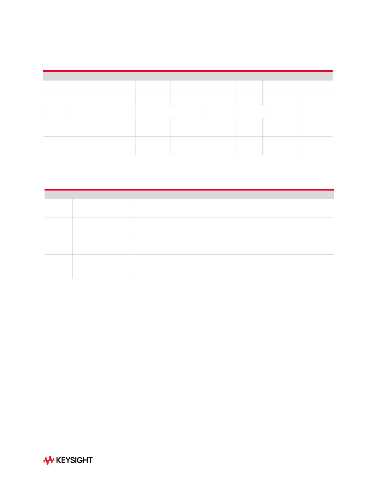
Module
Description
Comment
System control modules
34950A
64-bit digital I/O with memory
and counter
Eight 8-bit digital I/O channels with programmable polarity, thresholds up to 5 V, with handshaking
protocols, and pattern memory. Two 10 MHz frequency counter and programmable clock output to 20 MHz
34951A
4-channel isolated D/A
converter with waveform
memory
Output DC voltage up to ± 16 V or DC current up to ± 20 mA.
Output waveforms with a 200 kHz update rate and 16 bits of resolution.
Use on-board memory to create point-to-point waveforms with more than 500,000 points.
34952A
Multifunction module with 32-
bit DIO, 2-ch D/A, and
totalizer
Four 8-bit digital I/O channels, two ± 12-V analog outputs, and a 100 kHz gated totalizer.
34959A
Breadboard component
module
Create your own custom designs with access to the +12 V and +5 V supplies, 16 GPIO ports, 4 Analog Bus
drivelines, and 28 relay drivelines.
Alternatively, you may use the 4 Analog Bus drivelines as 4 additional general-purpose relay drivelines.
Refer to Internal DMM / Analog Bus ratings.
Module Description Insertion loss Isolation Freq range VSWR
Input
impedance
Comments
RF and microwave modules
34941A
Quad 1x4 50 ohm 3 GHz RF
multiplexer
0.6 dB > 58 dB 3 GHz < 1.25 50 Ω @ 1 GHz
34942A
Quad 1x4 75 ohm 1.5 GHz RF
multiplexer
0.6 dB > 60 dB 1.5 GHz < 1.35 75 Ω @ 1 GHz
34945A /
34945EXT
Microwave switch/attenuator
driver
Can drive up to 64 external switch coils; 32 SPDT switches, 8 multiport switches, 8 attenuators, or your
own combination. Expand with additional 34945EXTs
34946A
Dual 1x2 SPDT terminated
microwave switch
< 0.42 dB
< 0.69 dB
< 0.8 dB
> 85 dB
> 67 dB
> 60 dB
4 GHz or 20
GHz
26.5 GHz
< 1.15
< 1.30
< 1.6
50 Ω
@ 4 GHz
@ 20 GHz
@ 26.5 GHz
34947A
Triple 1x2 SPDT unterminated
microwave switch
< 0.42 dB
< 0.69 dB
< 0.8 dB
> 85 dB
< 0.69 dB
< 0.8 dB
4 GHz or
20 GHz
26.5 GHz
< 1.15
< 1.30
< 1.6
50 Ω
@ 4 GHz
@ 20 GHz
@ 26.5 GHz
11
34980A Multiplexer Switch Modules
The 34980A multiplexer modules can be used to connect one of many different points to a single point.
You can connect to an external instrument or scan multiple analog signals to the internal DMM.
Choose from the following features:
•
1-wire, 2-wire, or 4-wire configurations
•
High voltage—up to 300 V, 1 A
•
High density—70 2-wire or 80 1-wire channels
•
Scan up to 1000ch/sec with the 34925A
•
Bandwidths up to 45 MHz
•
Temperature measurements with built-in thermocouple reference junction (34921T)
•
AC or DC current measurements without external shunts
•
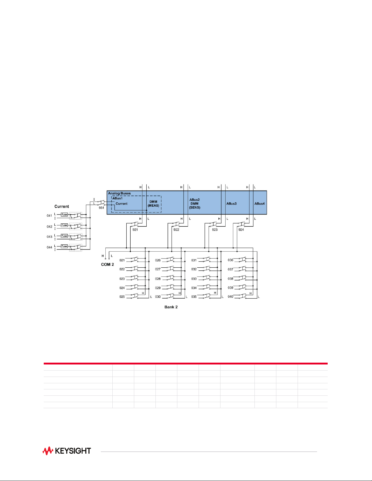
Flexible connections via standard 50- or 78- pin Dsub cables or detachable terminal blocks
Figure 2. 34921A 40-channel armature multiplexer with low thermal offset (bank 2)
Voltage
AC/DC
Current
AC/DC
Freq/
Period
Ω 2-
Wire
Ω 4-
Wire
Thermocouple
RTD
2-Wire
RTD
4-Wire
Thermistor
34921A Armature Multiplexer
Yes
Yes
Yes
Yes
Yes
Yes
Yes
Yes
Yes
34922A Armature Multiplexer
Yes
No
Yes
Yes
Yes
Yes
Yes
Yes
Yes
34923A Reed Multiplexer (2-wire)
Yes
No
Yes
Yes
Yes
Yes
Yes
Yes
Yes
34923A Reed Multiplexer (1-wire)
Yes
No
Yes
Yes
No
Yes
Yes
No
Yes
34924A Reed Multiplexer
Yes
No
Yes
Yes
Yes
Yes
Yes
Yes
Yes
34925A FET Multiplexer (2-wire)
Yes
No
Yes
Yes
Yes
Yes
No
Yes
No
34925A FET Multiplexer (1-wire)
Yes
No
Yes
Yes
No
Yes
No
No
No
Note: See user’s guide for additional information
12
Multiple multiplexers can connect to the built-in analog buses, allowing you to scan up to 560 2-wire
channels or 640 1-wire channels in a single mainframe. The 34921A also offers 4 channels for directly
measuring current. Or, if you need more current channels, shunts can be added to the terminal block for
easy current measurements.
The multiplexer modules feature break-before-make connections to ensure that no two signals are
connected to each other during a scan. Or, if you prefer, you can control switching manually to create
your own switch configuration. All the multiplexer switches have a relay counter to help predict when
relays need to be replaced.
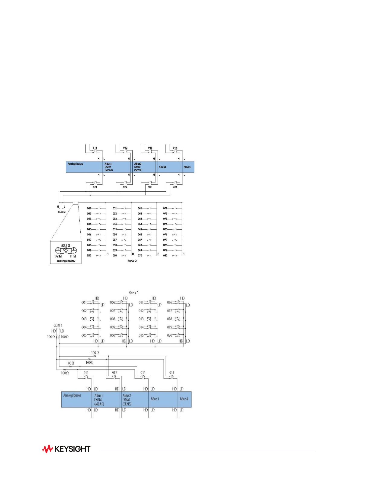
Note: The 34923A and 34924A have 100-ohm input protection resistors that limit current and
protect the reed relays.
Figure 3. 34925A 40/80-channel optically isolated FET mux (shown in 1-wire mode bank 2)
Figure 4. 34923A 40 channel reed multiplexer (bank 1 shown)