技术资料.pdf - 第16页
16 Matr ix swit ch modu les 34931A 34932A 34933A 34934A Channe ls/con figu ration s dual 4x8 8x8 4x16 dual 4x16 8x16 4x32 dual 4x8 8x8 4x16 quad 4x8, 1 - wire quad 4x3 2 4x128 8x64 16x32 Swit ch type Armat ure latchi ng …
15
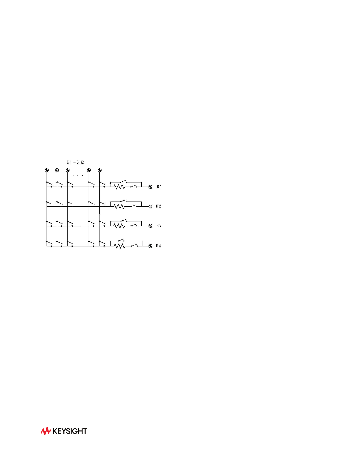
The 34933A also has in-rush resistors on each column for added protection. The 34934A also has in-rush
protection resistors but also has an automatic bypass switch for flexibility in making low-level
measurements. Row disconnect switches also reduce the capacitance loading when combining modules
to create larger matrices.
Multiple matrix modules can be combined through the analog bus or the row expansion kit (34934A only)
to create a larger matrix. The matrix can then be connected to the internal DMM for easy measurements.
Combine your matrix with a multiplexer switch to achieve the desired switching topology and get a lower-
cost solution with better specifications. All the matrix switches include a relay counter to help predict when
relays need to be replaced. Use the sequencing feature to easily change between different cross-point
setups.
NOTE: The 34933A and 34934A have 100-ohm input protection resistors to limit current and protect the
reed relays.
Figure 6. 34934A quad 4x32 matrix (1 of 4 matrices shown)

16
Matrix switch modules
34931A
34932A
34933A
34934A
Channels/configurations
dual 4x8
8x8
4x16
dual 4x16
8x16
4x32
dual 4x8
8x8
4x16
quad 4x8, 1-wire
quad 4x32
4x128
8x64
16x32
Switch type
Armature latching
Armature latching
Reed non-latching
Reed non-latching
Input characteristics (per channel)
Max volts
± 300 V
1, 13
± 300 V
1, 13
± 150 Vpeak
2, 14
± 100 Vpeak
Max current (DC, AC RMS)
Switch current
1 A
1 A
0.5 A
5
/0.05 A
8
0.5 A
Carry current
2 A
2 A
1.5 A
5
/0.05 A
8
0.5 A
Power (VA)
6
60 VA
60 VA
10 VA
7, 8, 9
10 VA
2, 8, 10
Volt-Hertz limit
10^8
10^8
10^8
10^8
Initial closed channel res
3
< 1.5 Ω
< 1.5 Ω
< 1.5 Ω
5
/200 Ω
8
nominal
< 1Ω/100 Ω
8, 10
General Specifications
Offset voltage 3 < 3 uV < 3 uV
< 50 uV
< 100 uV 1-wire
< 20 uV
< 50 uV 1-wire
DC Isolation (ch-ch, ch-earth)
> 10G Ω
12
> 10G Ω
12
> 10G Ω
10G Ω
AC characteristics
Bandwidth at terminal block
4
30 MHz 30 MHz
30 MHz
5
/4 MHz
8
2 MHz 1-wire
35 MHz 2-wire
15 MHz 1-wire
Crosstalk at terminal block (ch-ch)
4
300 kHz
–65 dB –65 dB –65 dB –65 dB
1 MHz
20 MHz
–55 dB
–30 dB
–55 dB
–30 dB
–55 dB
–40 dB
–55 dB
–33 dB
Capacitance at terminal block
HI-LO
LO – earth
50 pF
80 pF
50 pF
80 pF
80 pF
75 pF
45 pF
250 pF
General characteristics
Relay life, typical
No-load
100 M 100 M 1000 M
1000 M operations
10 V, 100 mA
Rated load
10 M
100 k
10 M
100 k
10 M
10 k
Open/close time
4 ms/4 ms
4 ms/4 ms
0.5 ms/0.5 ms
0.35 ms/0.10 ms
Analog bus backplane connection
Bank 2
Bank 2
Bank 2
No
Notes:
1. DC or AC RMS voltage, channel-to-channel or channel-to-earth
2. Peak voltage, channel-to-channel or channel-to-earth
3. Into analog bus. System errors are included in the internal DMM measurement accuracy specifications
4. 50 Ω source, 50 Ω load, differential measurements verified (Sdd21)
5. With input resistors bypassed. Bypassing resistors will reduce the lifetime of relays. See the rated load relay life
characteristics.
6. Limited to 6 W channel resistance power loss per module
7. Power restrictions allow only 20 channels to be closed at one time
8. Protection Resistors:
9. 34933A - 100Ω ± 5%; 0.5W; TC = ±200ppm/°C.
10. 34934A - 100Ω ± 1%; 0.25W; TC = ±100ppm/°C.
11. If this resistance is not bypassed in the low side source line of 4-wire resistance measurement, the 100 Ω range is
limited.
12. Channel resistance is typically < 1.5 Ω but can go as high as 50 Ω when a channel is used in measurement
applications with < 10 mA load current. Increased relay channel resistance for measurements with load currents
below 10 mA can occur on cards that have been out of service or following relay inactivity for periods of greater
than 1 week. Switching relays for 2K cycles prior to use may reduce the variation in channel resistance. Applies to
the 34931A and 34932A. Keysight recommends the use of 4-wire Ohms for resistance measurements. For high
accuracy voltage measurements, select the DMM input resistance setting of > 10 G ohms to minimize the impact of
relay contact resistance.
13. Pollution Degree 1 ±300Vrms or VDC; Pollution Degree 2 ±100Vrms or VDC
14. Pollution Degree 1 ±150Vpeak; Pollution Degree 2 ±100Vpeak
17
34980A General-Purpose Switch Modules
The 34980A general-purpose switches can be used to route signals or to control other system devices.
These switches are ideal for device actuation and switching loads or power supplies.
Choose from the following features:
•
Form C channels up to 1 A, 60 VA
•
Form A channels up to 5 A, 150 VA
•
Armature latching relays
•
Simultaneous channel switching
•
Temperature sensor to detect overheating conditions
•
Connections via standard 50 or 78-pin Dsub cables or detachable terminal block
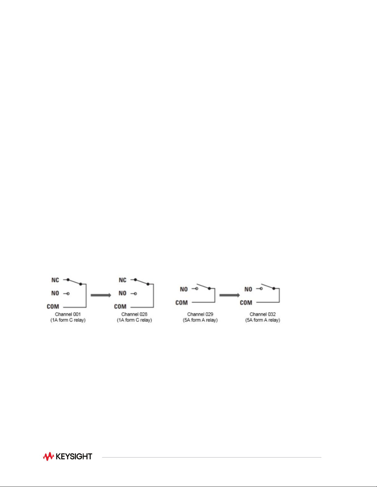
The 34937A is the most versatile general-purpose switch with 28 Form C channels that can switch up to 1
A of current. In addition, this module has four Form A channels that can switch up to 5 A of current. For
power switching applications, the 34938A has 20 5-amp channels in a Form A topology. Each Form A
general-purpose switch can handle up to 150 W, enough for many power line switching applications. For
high-density applications, the 34939A offers 64 Form A channels for switching up to 1A and carrying
currents up to 2A.
The general purpose switches contain latching armature relays where multiple channels can be closed at
the same time. Additionally, for switching reactive loads, the optional terminal blocks have pads for
snubbing circuits.
The built-in relay counter helps predict when relays need to be replaced.
Figure 7. 34937A 32-channel Form A / Form C