技术资料.pdf - 第24页
24 34945EXT switch drive (64 channels, low side drive mode) General specifications Driver off v oltage (max) 30 V Driver off l eakage current 500 μA Driver on current (max) 600 mA Driver on v oltage (max) 0.5 V @ 600 mA …
23
34945A/34945EXT Microwave Switch/Attenuator
Driver
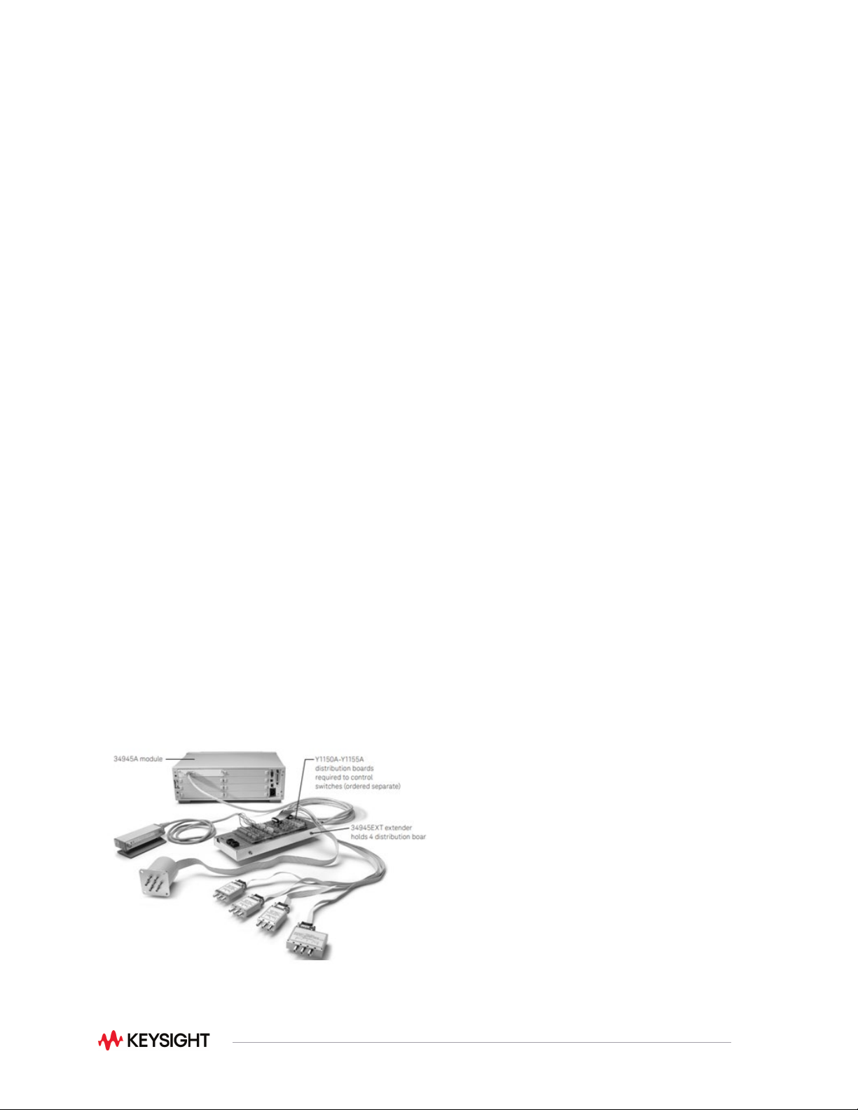
This module allows you to control switches, attenuators, and other devices external to the 34980A. The
34945A / 34945EXT provides the power and control signals for many of the most popular microwave
switches and attenuators. One 34945A /34945EXT combination can drive up to 64 switch coils—that’s 32
standard SPDT switches. The 34945A /EXT can be extended by adding additional 34945EXT boards.
The first 34945EXT is powered by the mainframe. You can add up to seven additional 34945EXT boards
with user-supplied power. Multiple switch operations are performed in sequential order, or for faster,
simultaneous switching, you can connect an external power supply to the 34945EXT.
The Y1150A-Y1155A distribution boards enable simple connections to the external switches. The
distribution boards plug onto the 34945EXT and are used to route the power and control signals from the
driver module to the switches using standard cables.
The 34945A /34945EXT also has sensing capabilities that allow a read back of the actual position of the
switch or attenuator. Drive signals for LED indicators are also provided to give a visual indication of the
switch position. The following microwave switches and attenuators are supported by the Y1150AY1155A
distribution boards:
•
N181x/U9397x series SPDT switches
•
8762/3/4 series SPDT switches (screw terminals)
•
8765x coaxial switches
•
8766x/8767x/8768x multiport switches
•
87104x/106x/L710xx/L720xx multiport switches
•
87406x series matrix switches
•
87204x/206x series multiport switches
•
87606x series matrix switches
•
87222x/L7222 transfer switches
•
849x and 8490x series attenuators
•
Other switches and devices through individual screw terminal connections
Figure 16. 34945A/34945EXT
24
34945EXT switch drive (64 channels, low side drive mode)
General specifications
Driver off voltage (max)
30 V
Driver off leakage current
500 μA
Driver on current (max)
600 mA
Driver on voltage (max)
0.5 V @ 600 mA
34945EXT switch drive (64 channels, TTL drive mode)
Hi output voltage
3 V @ Iout = 2 mA
Lo output voltage
0.4 V @ Iin = 20 mA
Lo input Current
20 mA
34945EXT position indicator sense inputs
Channels
64
Lo input voltage (max)
0.8 V
Hi input voltage (min)
2.5 V
Input resistance
> 100 kΩ @ Vin ≤ 5 V
> 20 kΩ @ Vin > 5 V
Maximum input voltage
30 V
34945EXT switch drive power supply (34945EXT powered by 34945A)
Voltage
24 V nominal (external power supply required for switches needing more than
24 V)
Current
100 mA continuous + 200 mA (15 msec pulse, 25% duty cycle)
34945EXT external power connection
Voltage range
4.75 V to 30 V
Current limit
2 A
LED indicator (Current mode divers)
Channels
64
Supply voltage
5 V nominal
LED drive current
5 mA nominal, (prog 1-20 mA)
Driver compliance voltage
0.8 V
34945EXT dimensions
Dimensions
11.2" x 4.5" x 1.5" high with distribution boards installed
Maximum of eight 34945EXT’s per mainframe
Switch drive control is also available in L4445A and L4490A/91A RF Switch Platform.
Note: See Configuration Guide, “34945A, L4445A, L4490A/L4491A” literature number 5989-2272EN, for configuration details.

25
34980A System Control Modules
34950A 64-bit digital I/O with memory and counter
This module can be used to simulate or detect digital patterns. It has eight 8-bit digital I/O channels with
handshaking, pattern memory, two 10 MHz counters with gate functions, and programmable clock output.
Digital input/output
The digital I/O bits are organized into two banks of 32-bits. The I/O bits can be configured and
programmed as inputs or outputs in 8-bit channels. The digital outputs can be configured as active drive
or open-drain outputs with a 10 kΩ pull up. User-supplied pull-up resistors for up to 5 V outputs are also
acceptable. The digital inputs have programmable thresholds up to 5 V for compatibility with most digital
logic standards.
The onboard pattern memory can be used to select and output digital stimulus or bit-stream patterns or to
capture external digital data. Each bank has independent memory and directional control so that one
bank can output data while the other captures data. The memory can be divided up to 64 Kbytes per 8-bit
channel.
Specifically, the digital I/O channels also have:
•
Variable active high drive output from 1.65 V to 5 V or open-drain
•
Variable input thresholds from 0 V to 5 V
•
Configurable handshaking protocols, including synchronous and strobe
•
Programmable polarity
•
Source or sink up to 24 mA with an Imax of 400 mA per module.
•
Internal alarming for maskable pattern match
•
1 hardware pattern interrupt per bank
•
Connections via standard 78-pin Dsub cables or detachable terminal block
Frequency counter/totalizer
The two channels can be used to count digital events, frequency, period, duty cycle, totalize, and pulse
width. The counter/totalizer also includes:
•
Programmable gate functionality
•
Programmable input thresholds levels 0 V to 3 V