技术资料.pdf - 第39页
39 Measurem ent Char acteris tics with Opti onal Internal DMM Measurement characteristics DC voltage Measurement method Continuou sly integrat ing multi - slope III A - D conver ter A- D linear ity 0.0002% o f reading + …
38
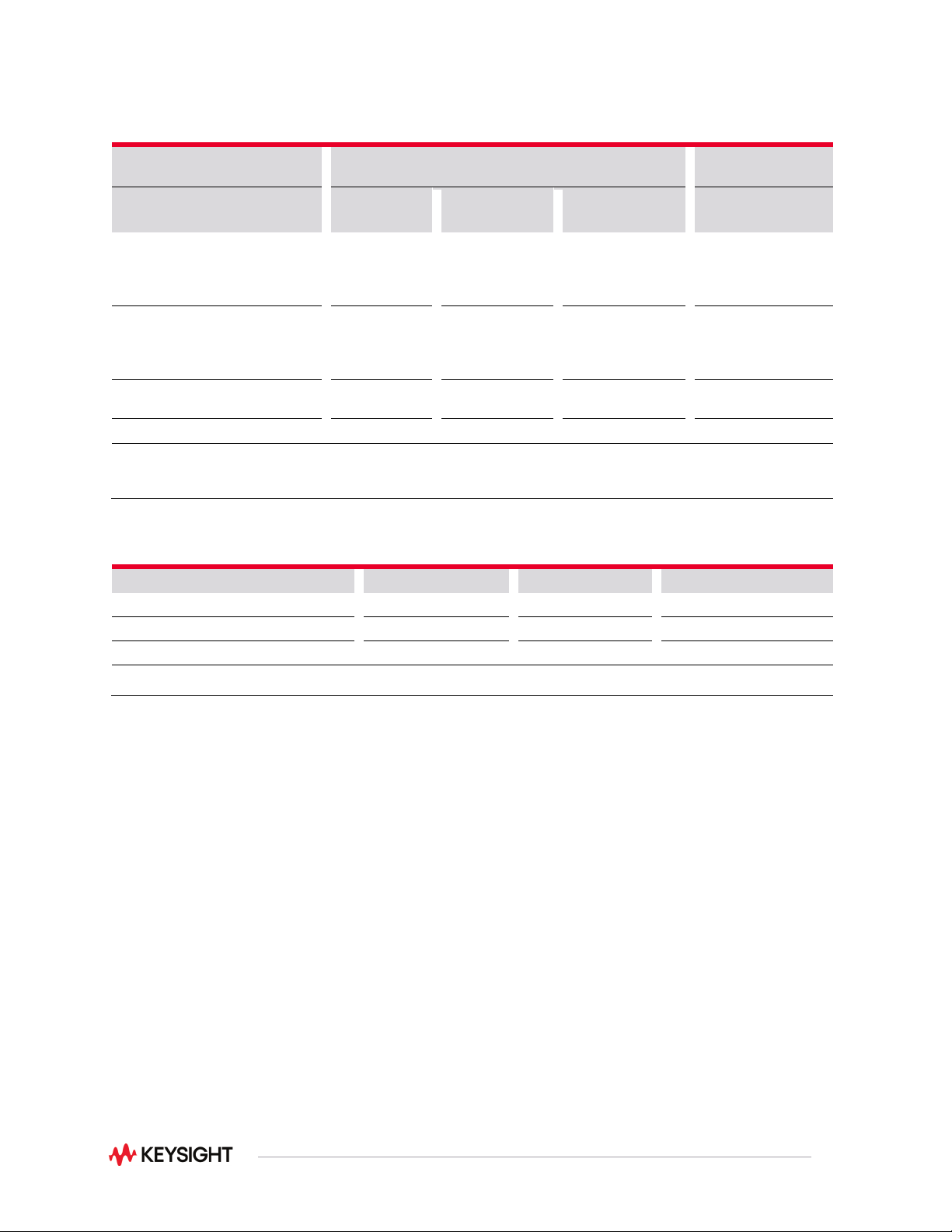
Scanning measurement rates to bus or memory
Direct measurements – direct to I/O (includes switch,
measure time and I/O time)
Measurement into
memory
Scanning channels
1
GPIB
ch/sec
USB 2.0 ch/sec
LAN (w VXI 11)
ch/sec
Into memory ch/sec
Scanning DCV or 2-wire ohms
34925A
34923A/24A
34921A/22A
920
588
109
860
572
109
980
605
109
1000
625
109
Scanning ACV
2
34925A
34923A/24A
34921A/22A
318
260
88
315
260
88
323
260
88
318
260
88
Scanning temperature
34921A
109
109
109
109
Scanning digital in 34950A
660
592
815
1038
Note:
1. Speeds are for 4 1/2 digits, delay 0, display off, autozero off and scanning is within bank on the same module; add
10ms for between banks or modules for 2-wire measurements; 4-wire measurements are slower
2. Add additional time for filter setting on ACV
Data out of memory to LAN, USB, or GPIB (data transfer rate with 1000 channel blocks)
GPIB rds/sec
USB 2.0 rds/sec
LAN (w VXI 11)
1
rds/sec
Readings
2560
2400
3542
Readings with timestamp
1304
1230
1826
Readings with all format options ON
980
926
1361
Note:
1. LAN large block throughput rate is increased by approximately 30% using LAN sockets
39
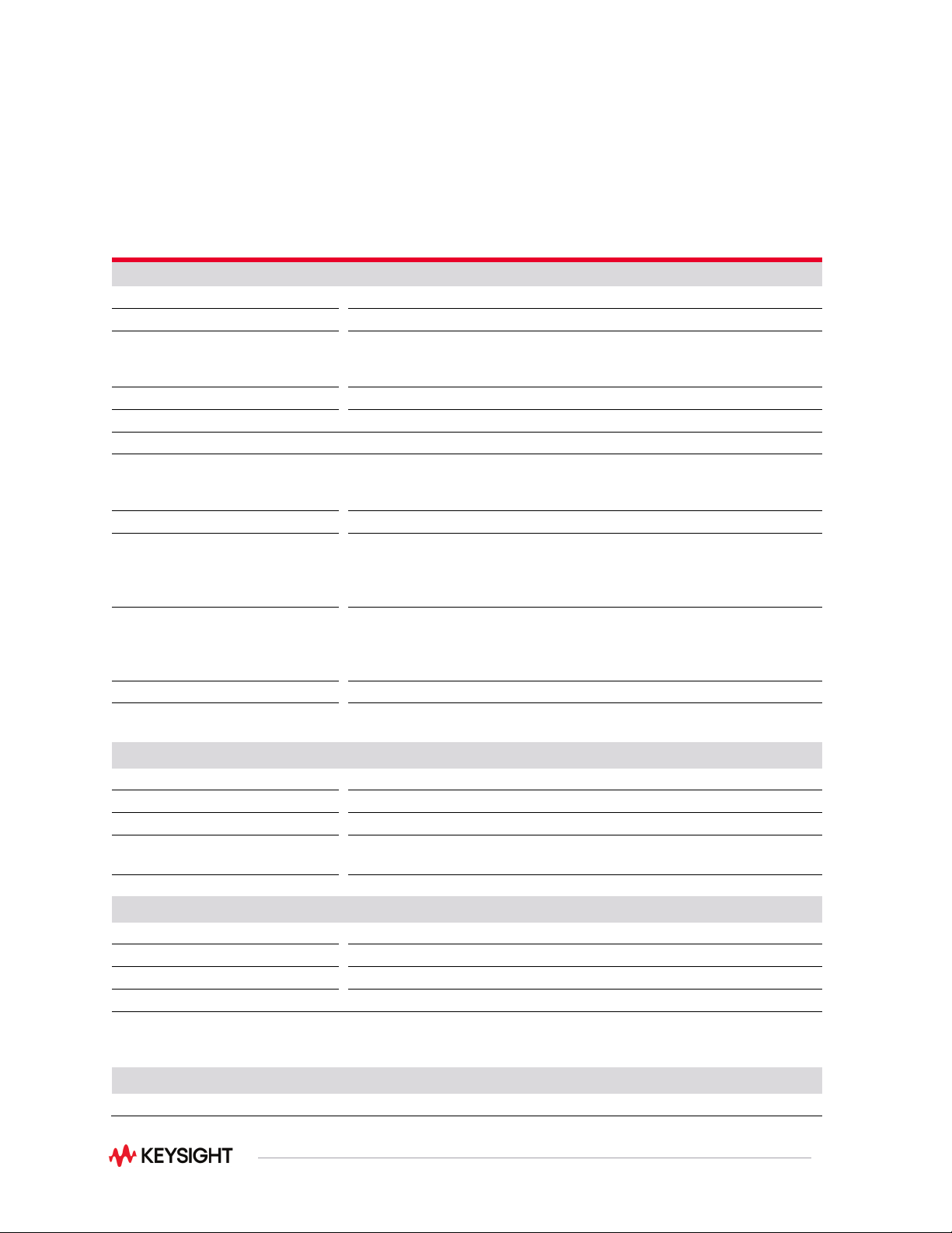
Measurement Characteristics with Optional
Internal DMM
Measurement characteristics
DC voltage
Measurement method
Continuously integrating multi-slope III A-D converter
A-D linearity
0.0002% of reading + 0.0001% of range on 10 V range
Input resistance
100 mV, 1 V, 10 V ranges 100 V,
300 V ranges
Selectable 10 M Ω or > 10,000 M Ω 10 M Ω ± 1%
Input bias current
< 50 pA at 25 °C
Input protection
300 V for Pollution Degree 1 and 100 V for Pollution Degree 2
True RMS AC voltage
Measurement method
AC coupled True RMS—measures the AC component of the input with up
to 300 VDC for Pollution Degree 1 and 100 VDC for Pollution Degree 2 of
bias on any range
Crest factor
Maximum of 5:1 at full scale
Additional crest factor errors (non-
sinewave)
Crest factor 1-2 0.05% of reading
Crest factor 2-3 0.15% of reading
Crest factor 3-4 0.30% of reading
Crest factor 4-5 0.40% of reading
AC filter bandwidth:
Slow
Medium
Fast
3 Hz - 300 kHz
20 Hz - 300 kHz
200 Hz - 300 kHz
Input impedance
1 M Ω ± 2% in parallel with 150 pF
Input protection
Pollution Degree 1: 300 Vrms all ranges
Pollution Degree 2: 100 Vrms all ranges
Resistance
Measurement method
Selectable 4-wire or 2-wire ohms
Current source
Referenced to LO input
Offset compensation
Selectable on 100 Ω, 1k Ω, 10 kΩ ranges
Maximum lead resistance
10% of range per lead for 100 Ω and 1k Ω ranges. 1k Ω on all other
ranges
Input protection
300 V for Pollution Degree 1 and 100 for Pollution Degree 2
Frequency and period
Measurement method
Reciprocal counting technique
Voltage ranges
Same as AC voltage function
Gate time
1 s, 100 ms, or 10 ms
Measurement timeout
Selectable 3 Hz, 20 Hz, 200 Hz LF limit
Measurement consideration (frequency and period): All frequency counters are susceptible to error when
measuring low-voltage, low-frequency signals. Shielding inputs from external noise pickup is critical for
minimizing measurement errors.
DC current
Shunt resistance
5 Ω for 10 mA, 100 mA; 0.1 Ω for 1 A

40
Input protection
1.5 A 250 Vac fuse on 34921A module
True RMS AC current
Measurement method
Direct-coupled to the fuse and shunt. AC coupled True RMS measurement
(measures the ac component only
Shunt resistance
5 Ω for 10 mA; 0.1 Ω for 100 mA, 1 A
Input protection
1.5 A 250 Vac, 50/60 Hz fuse on 34921A module
Thermocouple
Conversion
ITS-90 software compensation
Reference junction type
Internal, fixed, or external
Open thermocouple check
Selectable per channel. Open > 5 kΩ
Thermistor
44004, 44007, 44006 series
RTD
a = 0.00385 (DIN) and a = 0.00392
Measurement noise rejection 60/50 Hz
1
DC CMRR
AC CMMR
140 dB
70 dB
Integration time Normal mode rejection
2
200 plc/3.33 s (4 s)
100 plc/1.67 s (2 s)
20 plc/333 ms (400 ms)
10 plc/167 ms (200 ms)
2 plc/33.3 ms (40 ms)
1 plc/16.7 ms (20 ms)
< 1 plc
105 dB
3
100 dB
3
95 dB
3
90 dB
3
85 dB
60 dB
0 dB
Note:
1. For 1 kΩ unbalance in LO lead
2. For power line frequency ± 0.08%
3. For power line frequency ± 1% use 75 dB or ± 2.5% use 60 dB