技术资料.pdf - 第7页
7 Addition ally, sinc e the We b inter face is built int o the in strument, you can access it on any operati ng syst em that supports the Web brows er wit hout hav ing to ins tall any s pecia l softwar e. Pass word prote…

6
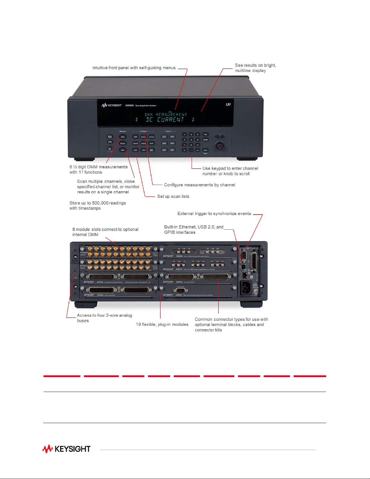
Modules Provide Flexible System Stimulus
and Control
System control—with analog outputs, open-collector digital outputs, clock generation, and isolated Form-
C relays for controlling external devices. Additionally, with the microwave switch/attenuator driver, high-
frequency switches and attenuators can be efficiently controlled externally to the 34980A mainframe.
Analog sources—output either voltage or current. You can configure the 4-channel isolated D/A converter
as a point-to-point arbitrary waveform generator that lets you define up to 500,000 points per waveform.
Digital patterns—send or receive digital data from your device under test. With onboard memory, you can
output communication protocols and bitstreams or monitor digital input patterns and interrupt when a
user-defined pattern is detected.
Standard Interfaces Take the Hassle Out of
Connecting to Your PC
Standard Ethernet, USB, and GPIB interfaces are included in every mainframe. Use one of the built-in
interfaces that are already available in your computer, or if you prefer, GPIB is still available.
•
USB offers the quickest and easiest connection scheme—it’s perfect for small systems and bench
connections.
•
Ethernet offers high-speed connections that allow for remote access and control. Choose a local
area network to filter out unwanted LAN traffic and speed up the I/O throughput. Or take advantage
of the remote capabilities and distribute your tests worldwide. Use the graphical Web browser to
monitor, troubleshoot, or debug your application remotely.
•
GPIB has many years of proven reliability for instrument communication and can be used in existing
GPIB-based test systems.
Remote Access and Control
The built-in Web browser interface provides remote access and control of the instrument via a Java
applet-enabled browser such as Internet Explorer version 11. Using the Web interface, you can set up,
troubleshoot, and maintain your system remotely:
•
View and modify instrument setup
•
Open, close, or monitor switches
•
Send SCPI commands
•
Define and execute switch scans and switch sequences
•
View error queue
•
Get status reports on relay counts, firmware revisions, and more
7
Additionally, since the Web interface is built into the instrument, you can access it on any operating
system that supports the Web browser without having to install any special software. Password protection
and LAN lock-out are also provided to limit access. The Web interface makes it easy to set up,
troubleshoot, and maintain your system remotely.
Work with your choice of software so you can save time and preserve your software and hardware
investments. Program directly with SCPI, or use IVI or LabVIEW software drivers that provide
compatibility with the most popular development environments and tools:
•
Keysight VEE Pro
•
National Instruments LabVIEW, LabWindows/CVI, TestStand, and Switch Executive
•
Microsoft Visual Studio.NET, C/C++, and Visual Basic 6
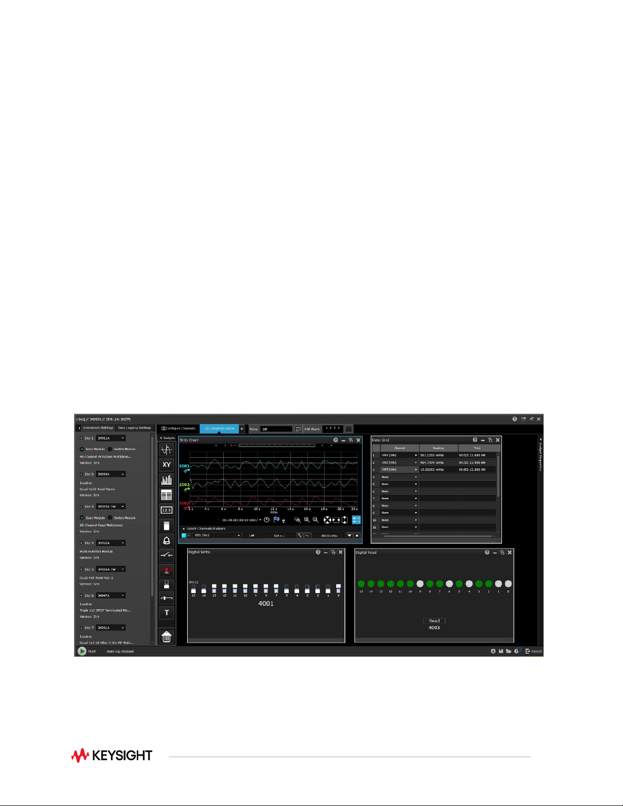
BenchVue Data Acquisition Control and Analysis
The BenchVue software platform enables you to easily connect to and control the 34980A using the
BenchVue DAQ application. This application enables you to quickly configure channels, log data, and
visualize measurements for 11 of the 21 plug-in modules. Simply identify the measurements you want to
acquire, initiate the process and see the data displayed in real-time. The rich set of colorful graphics
provides many options for analyzing and displaying your data. You can specify multiple channels per
graph or send collected data to multiple graphs. You can use strip charts with markers and alarm
indications or histograms with statistics. And, of course, you can use BenchVue to easily move data to
other applications for further analysis or for inclusion in your presentations and reports.
Figure 1. BenchVue DAQ
8
Power and Flexibility to Get Your Job Done
Analog Bus / Internal DMM
Max volts
Switch/Carry
current
BW
(MHz)
Power
(VA)
Volt-Hertz
limit
Max
Transients
4
Scan
ch/sec
Thermal
offset
Comments
± 300 V
1, 2
1A /2A
45 MHz
60 VA
3
10^8
1000Vpk
N/A
N/A
Config as
2- or 4-wire
Notes:
1. Pollution Degree 1 ±300 Vrms or VDC; Pollution Degree 2 ±100 Vrms or VDC.
2. DC or AC RMS voltage, channel-to-channel or channel-to-earth.
3. Limited to 6 W of channel resistance power loss per module.
4. Transient overvoltage is defined as a short duration overvoltage of a few milliseconds or less, oscillatory or non-
oscillatory, usually highly damped (IEC 61010-1).