技术资料.pdf - 第31页
31 Figure 18 . 34 952A multifunct ion module
30
34952A Multifunction Module with 32-bit DIO,
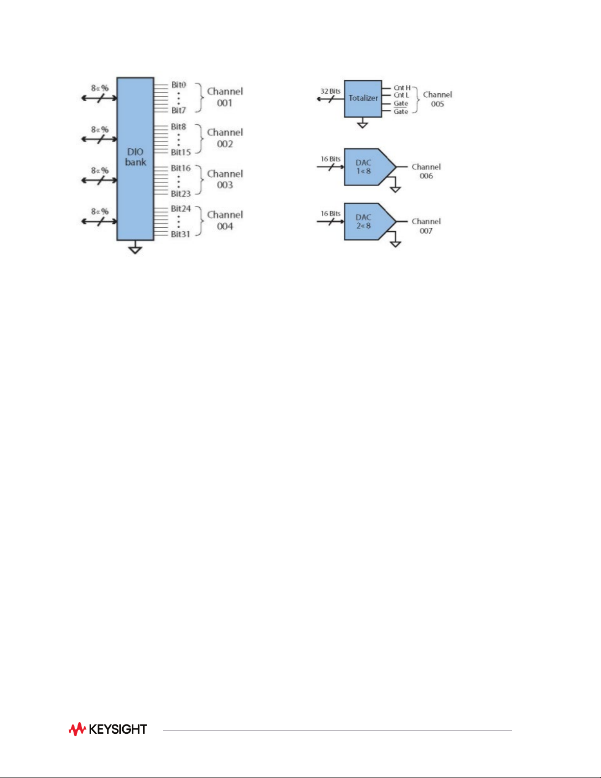
2-Channel D/A and Totalizer
The multifunction module offers the flexibility you need for system control. The 34952A has four 8-bit
digital I/O channels, a 100 kHz gated totalizer, and two ± 12 V analog outputs—all on a single earth-
referenced module. The digital inputs and totalizer input may be included in a scan list. Alarm limits for
the digital and totalizer inputs are evaluated continuously, capturing and logging alarm conditions even
between scans. Connections can be made via standard 50-pin Dsub cables or detachable terminal
blocks. The 34952T terminal block has a pinout for connection to an external Opto 22 board.
34952A multifunction module
Digital input/output characteristics
Channels
Four 8-bit channels, 8 bits wide, input or output, non–isolated
Vin(L)
< 0.8 V (TTL)
Vin(H)
> 2.0 V (TTL)
Vout(L)
< 0.8 V @ Iout = -400 mA per output
Vout(H)
> 2.4 V @ Iout = 1 mA
Vin(H) max
< 42 VDC with external open drain pull-up
Alarm
Maskable pattern match or state change
Speed
4 ms (max) alarm sampling
Latency
5 ms (typical) to 34980A alarm output
Read/write speed
95/s
Totalize input characteristics
Max count
2
26
-1
Totalize input
100 kHz (max) rising or falling edge, programmable
Signal level
1 Vp-p (min) 42 Vpk (max)
Threshold
0 V or TTL
Gate input
TTL-Hi, TTL-Lo, or none
Count reset
Manual or read + reset
Read speed
85 rds/s
Analog output characteristics
DAC 1,2
± 12 V, non-isolated
Resolution
1 mV
IOUT
10 mA max
Settling time
1 ms to 0.01% of output
Accuracy
1 year
± (% of output + mV)
(0.25% + 20 mV)
Temp. coefficient
± (0.015% + 1 mV)/
o
C

32
34959A Breadboard Component Module
Use this module to create your own custom designs inside the 34980A mainframe. You can control your
custom circuits with access to both the +12 V and +5 V supplies, 28 relay drive lines, and two 8-bit GPIO
ports. Your design can be isolated from the analog buses or connected by loading the backplane
switches. Simply mount your custom PC board or other components into the space provided and connect
via the two ribbon connectors provided. The module is provided with two 50- or 78-pin Dsub connector
openings. For custom connections, use the detachable flat faceplates for easy modification. You can
program your circuitry using standard read and write commands in SCPI.
34959A breadboard component module
General specifications
Max module power dissipation
6 W of channel resistance
Power available:
12 V regulation no load to full load
5 V regulation no load to full load
Max power from 12 V
Max power from 5V
10%
5%
6 W
1 W
Relay drives
Channels
28, sink up to 100 mA
Max Input Voltage
42 VDC
Leakage Current
8 µA
GPIO ports
Chan 1 and Chan 2
8 configure bits as input or output
Chan 3
3 output bits
High input
2 V min, 5.5 V max
Low input
0 V min, 0.8 V max
High output
2.4 V @ 4 mA, 3 V @ 500 µA
Low output
0.4 V @ 8 mA
34959A breadboard component module conditions of acceptability:
1. Follow local laws and regulations provided by the Authority Having Jurisdictions (AHJ). This
equipment is Certified as a component for use in other CSA Certified equipment where the
suitability of the combination is to be determined in the end use application.
2. When interconnecting the 34959A component module to the system components during installation,
the overall 34980A and all installed modules for the system and their maximum rated allowable
inputs default to the lowest rating of any one system component or module.
3. With *hazardous voltages anywhere in the overall 34980A and all installed modules use only female
D-Sub output connectors Keysight Part Number DB-50(F) 1253-5854 or DB-78(F) 1253-5007.