技术资料.pdf - 第20页
20 Figure 9 . 3494 1A ty pic al ini tial c ro sst alk Figure 10 . 34 941A typical i nitial insert ion loss Figure 11 . 34 941A typical i nitial VSWR Figure 12 . 34 942A typical i nitial cros stalk 34946A/47 A — From DC t…
19
34980A RF and Microwave Switch Modules
The 34980A offers a variety of RF and microwave switch modules—RF multiplexers, SPDT switching
from DC to 26.5 GHz, or a switch/ attenuator driver module that allows you to control switches or
attenuators external to the 34980A mainframe.
34941A/42A—from DC to 3 GHz
The RF switch modules can be used to switch signals from DC to 3 GHz and above. This can be useful
for switching signals between oscilloscopes, spectrum analyzers, network analyzers, and other RF test
equipment.
Choose from the following features:
•
50- or 75-ohm Quad 4-channel multiplexers
•
DC to 3 GHz
•
30 V, 0.5 A, 10 W
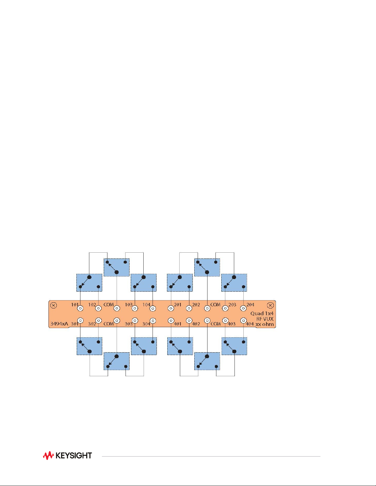
The 34941A and 34942A are configured as four independent 1x4 RF multiplexers on a single module.
Multiple banks can be connected together to create a larger multiplexer. To prevent ground loops,
individual multiplexers are isolated from each other and from the mainframe’s chassis. However, the
multiplexer channels can be chassis grounded with a simple change. Both 50-ohm and 75-ohm versions
are available.
Figure 8. 34941A Quad 1x4 50 ohm 3 GHz multiplexer
20
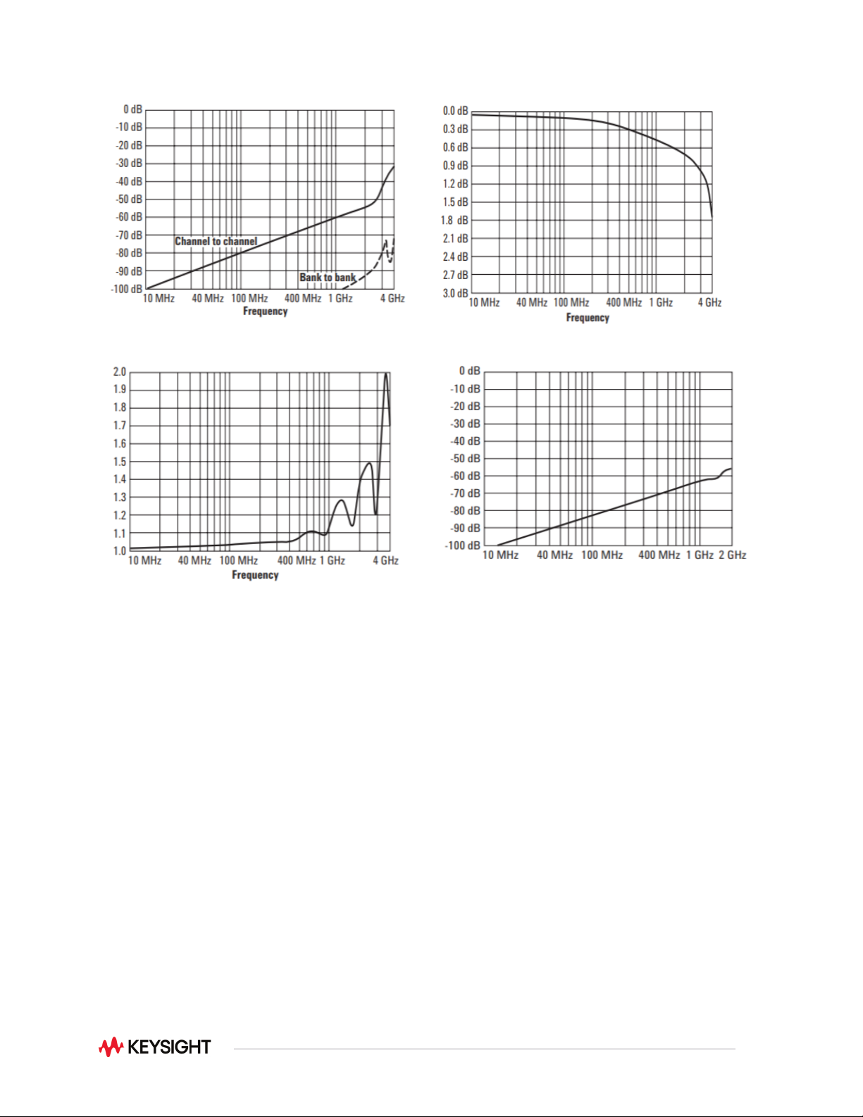
Figure 9. 34941A typical initial crosstalk
Figure 10. 34941A typical initial insertion loss
Figure 11. 34941A typical initial VSWR
Figure 12. 34942A typical initial crosstalk
34946A/47A—From DC to 26.5 GHz
For applications where you need only a few high-frequency switches, the 34946A and 34947A offer ingle-
pole, double-throw switches in either 4GHz, 20GHz or 26.5GHz options. These modules internally mount
two or three independent Keysight N1810 series coaxial switches. These switches are well known for
their excellent insertion loss, isolation, and VSWR specifications.
Switch read-back capabilities allow you to query the position of the switch. You can choose higher density
with the unterminated switches or select the terminated switches to maintain an impedance match.
21
34946A/47A Option 001
These modules can also be ordered without switches installed. This gives you the capability to install your
own N1810 series switches or use the module to control the N1810 Series switches outside the
mainframe.
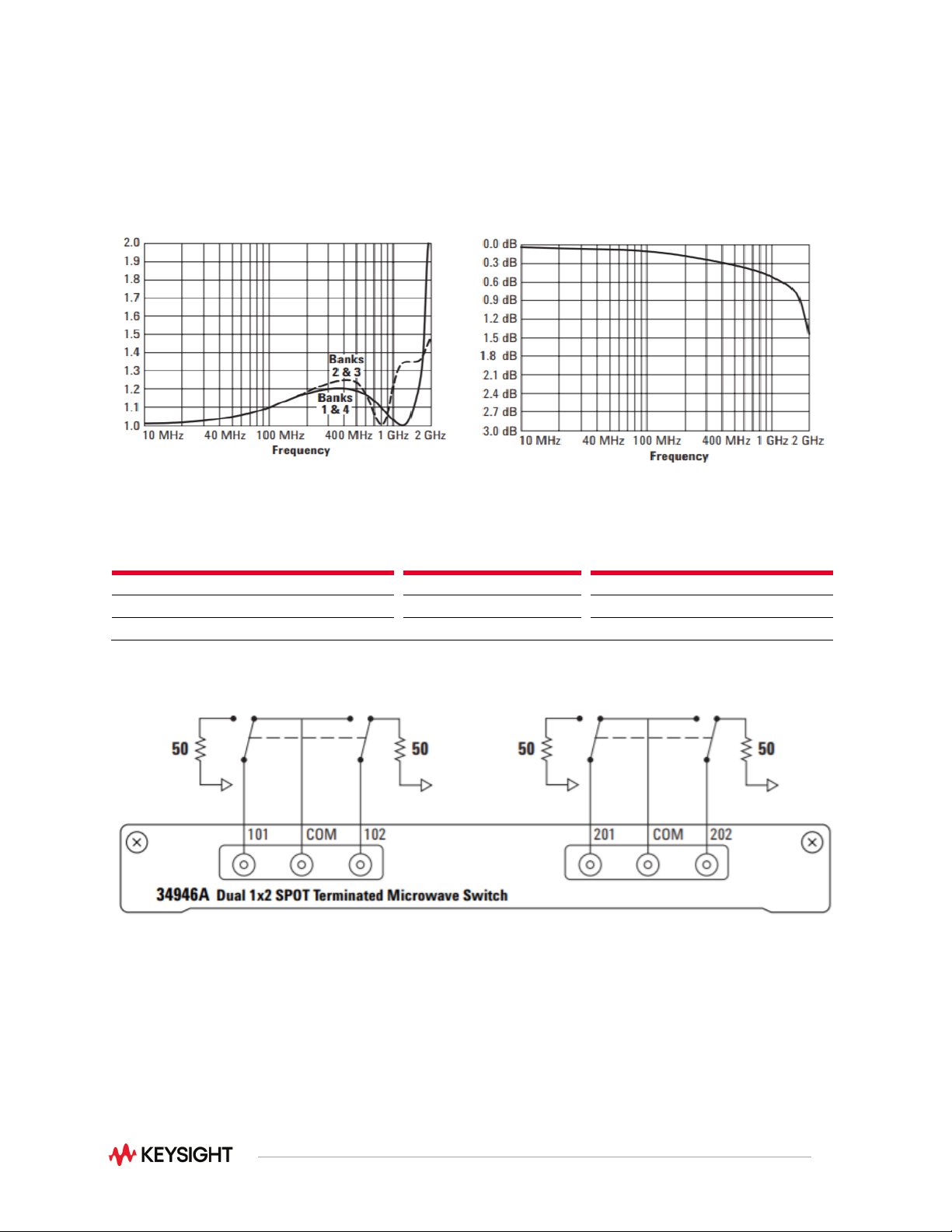
Figure 13. 34942A typical initial VSWR
Figure 14. 34942 typical initial insertion loss
N1810 minimum required switch options
Option
Comment
Coil Voltage
option 124
24 VDC coil
DC Connector
option 201
D” subminiature 9 pin female
Drive
option 402
Position indicators
Figure 15. 34946A Dual 1x2 SPDT terminated microwave switch