技术资料.pdf - 第19页
19 34980A RF a nd Microwave Sw itch Mo dules The 3498 0A offers a variet y of RF an d micr owave sw itch mod ules — R F multip lexer s, SPDT sw itching from DC to 26.5 GHz , or a switch/ at tenuator driver m odule t hat …
18
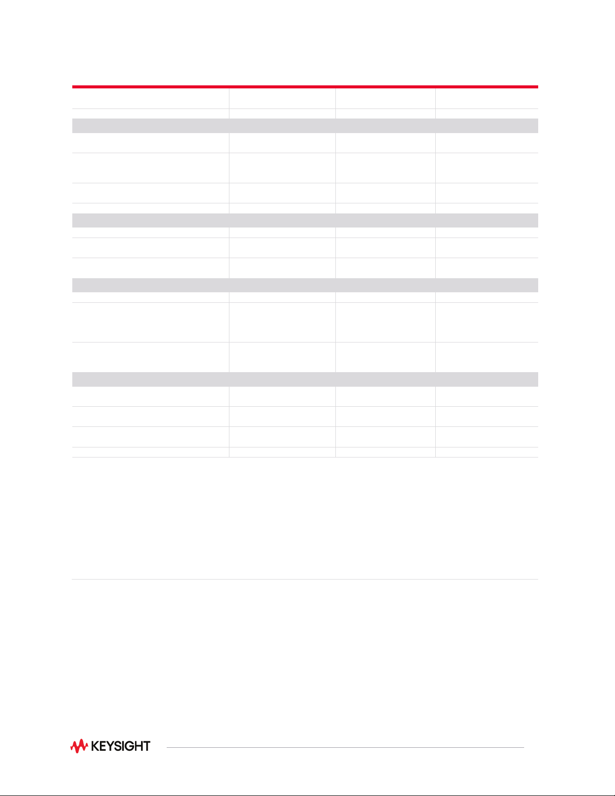
General purpose switch modules
34937A
34938A
34939A
Channels/configurations
28 Form C
4 Form A
20 Form A 64 Form A
Switch Type
Armature, latching
Armature, latching
Armature, latching
Input characteristics (per channel)
Max volts
(DC, AC RMS, Peak)
Form C – 300 VAC/DC
1, 4, 7
Form A – 30 VDC/250 VAC
5
30 VDC/250 VAC
1, 5
+/- 100 V peak
6
Max current
(DC, AC RMS, Peak)
Form C – 1 A (2 A carry)
Form A – 5 A switch
(7 A carry)
5 A switch
(7 A carry)
1 A switch
(2 A carry)
Power (VA)
2
Form C – 60 VA
Form A – 150 VA
150 VA 60 VA
Volt-Hertz limit
10
8
10
8
10
8
General specifications
Offset voltage
3 µV
3 µV
3 µV
Initial closed channel resistance
8
Form C – 125 mΩ
Form A – 50 mΩ
< 60 mΩ < 125 mΩ
CD isolation
(ch-ch, ch-earth)
> 10 GΩ > 10 GΩ 10 GΩ
AC characteristics
Bandwidth at terminal block
3
10 MHz
1 MHz
10 MHz
Channel isolation at terminal block
3
100 kHz
1 MHz
10 MHz
55 dB
35 dB
15 dB
60 dB
40 dB
45 dB
25 dB
5 dB
Capacitance at terminal block
CH - CH
CH - earth
Form C 12 pF, Form A 10 pF
Form C 21 pF, Form A 18 pF
65 pF
105 pF
20 pF
70 pF
General characteristics
Relay life no-load/rated
Form C – 100 M/100 k
Form A – 50 M/30 k
50 M/30 k > 100 M/100 k
Open/close time
Form C – 4 ms/4 ms
Form A – 10 ms/10ms
10 ms/10ms 4 ms/4ms
Initial/reset relay state
Form C- maintain state
Form A – user-configurable
User-configurable Maintain
Analog bus backplane connection
No
No
No
Notes:
1. DC or AC RMS voltage, channel-to-channel or channel-to-earth
2. Limited to 6 W of channel resistance power loss per module
3. 50 Ω source, 50 Ω load, differential measurements verified (S21)
4. Pollution Degree 1 ±300Vrms or VDC; Pollution Degree 2 ±100Vrms or VDC
5. Pollution Degree 1 ±250Vrms or VDC; Pollution Degree 2 ±100Vrms or VDC
6. Peak voltage, channel-to-channel or channel-to-earth
7. Differential Voltage FormC – FormA:
Pollution Degree 1 300Vrms or Vdc
Pollution Degree 2 100Vrms or VDC
8. Channel resistance is typically < 1.5 Ω but can go as high as 50 Ω when a channel is used in measurement
applications with < 10 mA load current. Increased relay channel resistance for measurements with load currents
below 10 mA can occur on cards that have been out of service or following relay inactivity for periods of greater
than 1 week. Switching relays for 2K cycles prior to use may reduce the variation in channel resistance. Applies to
the 34937A, 34938A and 34939A
19
34980A RF and Microwave Switch Modules
The 34980A offers a variety of RF and microwave switch modules—RF multiplexers, SPDT switching
from DC to 26.5 GHz, or a switch/ attenuator driver module that allows you to control switches or
attenuators external to the 34980A mainframe.
34941A/42A—from DC to 3 GHz
The RF switch modules can be used to switch signals from DC to 3 GHz and above. This can be useful
for switching signals between oscilloscopes, spectrum analyzers, network analyzers, and other RF test
equipment.
Choose from the following features:
•
50- or 75-ohm Quad 4-channel multiplexers
•
DC to 3 GHz
•
30 V, 0.5 A, 10 W
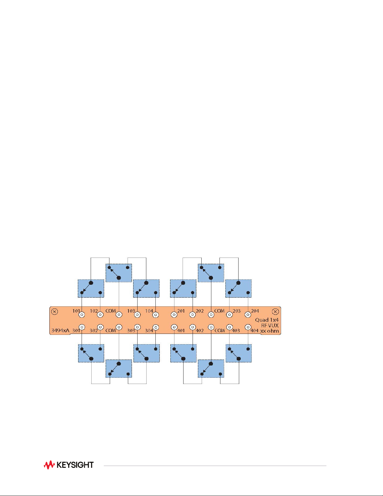
The 34941A and 34942A are configured as four independent 1x4 RF multiplexers on a single module.
Multiple banks can be connected together to create a larger multiplexer. To prevent ground loops,
individual multiplexers are isolated from each other and from the mainframe’s chassis. However, the
multiplexer channels can be chassis grounded with a simple change. Both 50-ohm and 75-ohm versions
are available.
Figure 8. 34941A Quad 1x4 50 ohm 3 GHz multiplexer
20
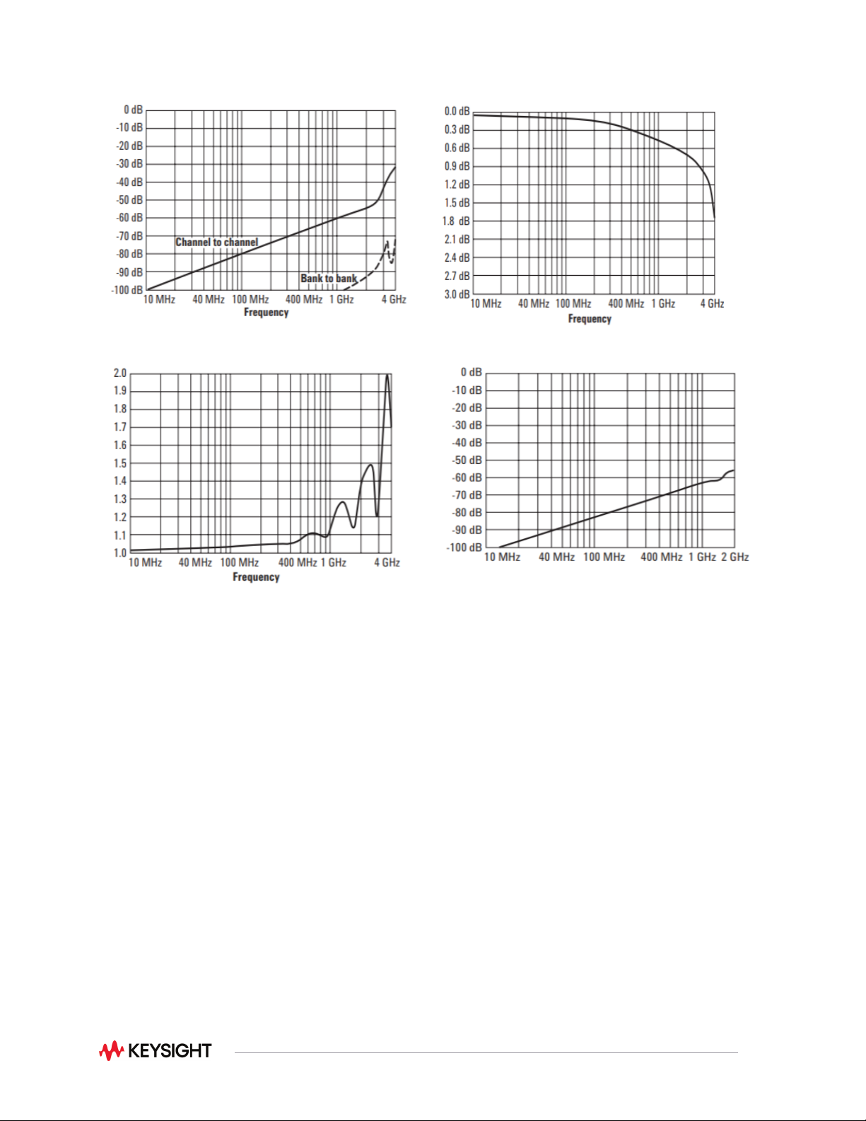
Figure 9. 34941A typical initial crosstalk
Figure 10. 34941A typical initial insertion loss
Figure 11. 34941A typical initial VSWR
Figure 12. 34942A typical initial crosstalk
34946A/47A—From DC to 26.5 GHz
For applications where you need only a few high-frequency switches, the 34946A and 34947A offer ingle-
pole, double-throw switches in either 4GHz, 20GHz or 26.5GHz options. These modules internally mount
two or three independent Keysight N1810 series coaxial switches. These switches are well known for
their excellent insertion loss, isolation, and VSWR specifications.
Switch read-back capabilities allow you to query the position of the switch. You can choose higher density
with the unterminated switches or select the terminated switches to maintain an impedance match.