技术资料.pdf - 第12页
12 Multiple multiplex ers c an connect to the bui lt - in an alog bus es, al lowing y ou to sc an up to 560 2 - wir e channels or 640 1 - wire ch annels in a singl e mainf rame. The 3 4921A als o off ers 4 c hannels for …
11
34980A Multiplexer Switch Modules
The 34980A multiplexer modules can be used to connect one of many different points to a single point.
You can connect to an external instrument or scan multiple analog signals to the internal DMM.
Choose from the following features:
•
1-wire, 2-wire, or 4-wire configurations
•
High voltage—up to 300 V, 1 A
•
High density—70 2-wire or 80 1-wire channels
•
Scan up to 1000ch/sec with the 34925A
•
Bandwidths up to 45 MHz
•
Temperature measurements with built-in thermocouple reference junction (34921T)
•
AC or DC current measurements without external shunts
•
Flexible connections via standard 50- or 78- pin Dsub cables or detachable terminal blocks
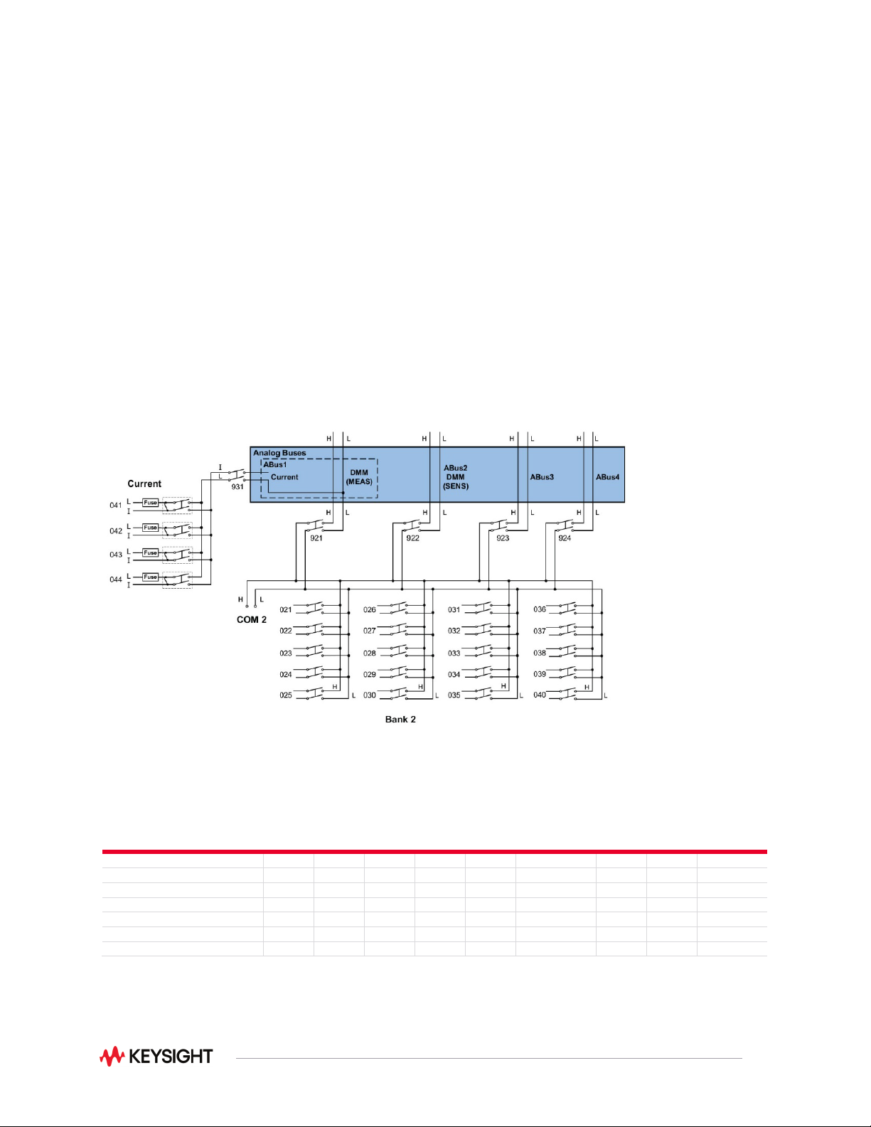
Figure 2. 34921A 40-channel armature multiplexer with low thermal offset (bank 2)
Voltage
AC/DC
Current
AC/DC
Freq/
Period
Ω 2-
Wire
Ω 4-
Wire
Thermocouple
RTD
2-Wire
RTD
4-Wire
Thermistor
34921A Armature Multiplexer
Yes
Yes
Yes
Yes
Yes
Yes
Yes
Yes
Yes
34922A Armature Multiplexer
Yes
No
Yes
Yes
Yes
Yes
Yes
Yes
Yes
34923A Reed Multiplexer (2-wire)
Yes
No
Yes
Yes
Yes
Yes
Yes
Yes
Yes
34923A Reed Multiplexer (1-wire)
Yes
No
Yes
Yes
No
Yes
Yes
No
Yes
34924A Reed Multiplexer
Yes
No
Yes
Yes
Yes
Yes
Yes
Yes
Yes
34925A FET Multiplexer (2-wire)
Yes
No
Yes
Yes
Yes
Yes
No
Yes
No
34925A FET Multiplexer (1-wire)
Yes
No
Yes
Yes
No
Yes
No
No
No
Note: See user’s guide for additional information
12
Multiple multiplexers can connect to the built-in analog buses, allowing you to scan up to 560 2-wire
channels or 640 1-wire channels in a single mainframe. The 34921A also offers 4 channels for directly
measuring current. Or, if you need more current channels, shunts can be added to the terminal block for
easy current measurements.
The multiplexer modules feature break-before-make connections to ensure that no two signals are
connected to each other during a scan. Or, if you prefer, you can control switching manually to create
your own switch configuration. All the multiplexer switches have a relay counter to help predict when
relays need to be replaced.
Note: The 34923A and 34924A have 100-ohm input protection resistors that limit current and
protect the reed relays.
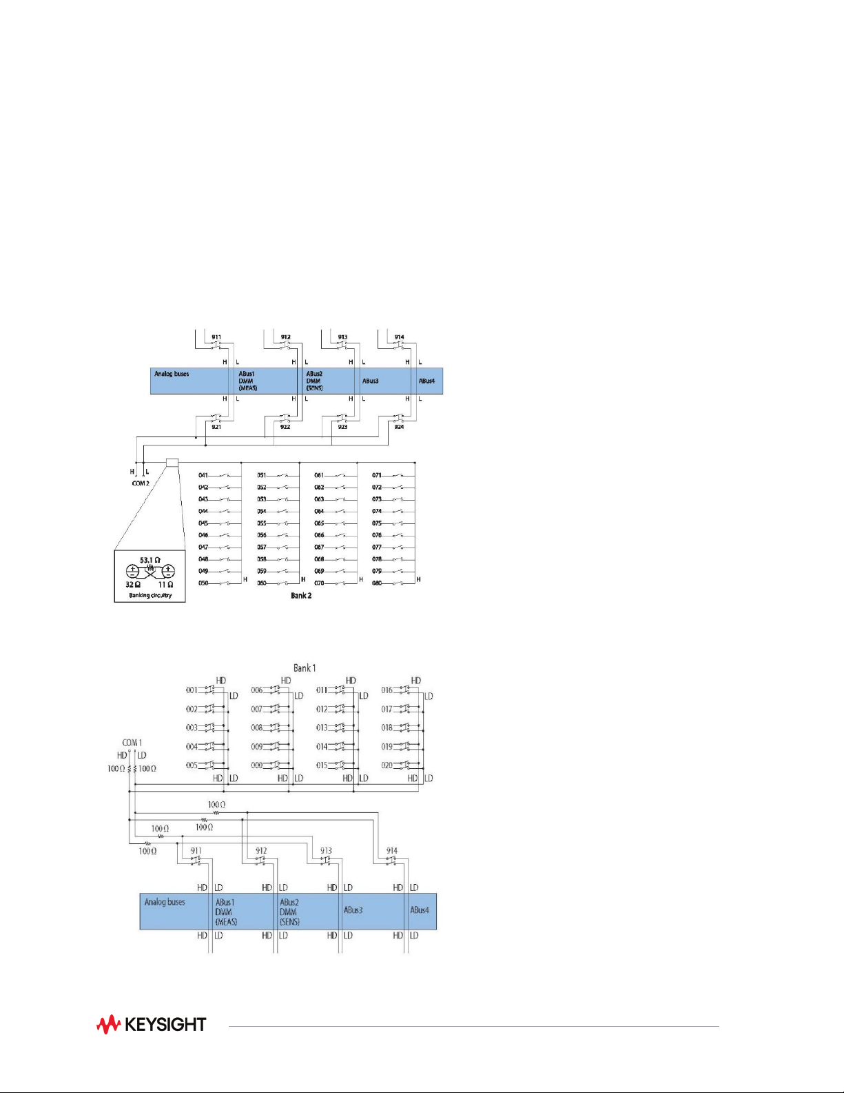
Figure 3. 34925A 40/80-channel optically isolated FET mux (shown in 1-wire mode bank 2)
Figure 4. 34923A 40 channel reed multiplexer (bank 1 shown)
13
Multiplexer switch modules
34921A
34922A
34923A
34924A
34925A
Channels/configurations
40 2-wire
20 4-wire
4-current
1.5 A Fused
70 2-wire
35 4-wire
80 1-wire
40 2-wire
20 4-wire
70 2-wire
35 4-wire
80 1-wire
40 2-wire
20 4-wire
Switch type
Armature latching
Armature latching
Reed
Reed
Optically isolated FET
Input characteristics (per channel)
Max volts
± 300 V
1, 13
± 300 V
1, 13
± 150 V peak
2, 14
± 150 V peak
2, 14
± 80 V peak
2
Max current
(DC, AC RMS)
Switch current
1 A 1 A 0.5 A
5
/ 0.05 A
11
0.5 A
5
/ 0.05 A
11
0.02 A
8
Carry current
2 A
2 A
1.5 A
5
/ 0.05 A
11
1.5 A
5
/ 0.05 A
11
Power (VA)
6
60 VA
60 VA
10 VA
10 VA
1.6 VA
Volt-Hertz limit
10^8
10^8
10^8
10^8
10^7
Initial closed channel res
3
< 1.5 Ω
12
< 1.5 Ω
12
< 1.5 Ω
5
/200
11
nominal
< 1.5 Ω
5
/200
11
Nominal
< 700 Ω
11
General specifications
Offset voltage
3
< 3 μV < 3 μV
< 50 μV
< 100 uV 1-wire
< 50 uV < 3 μV
DC Isolation (ch-ch, ch-earth)
> 10 GΩ
> 10 GΩ
> 10 GΩ >
10 GΩ
> 10 GΩ
Leakage current
3
N/A
N/A
N/A
N/A
20 nA
9
T/C cold junction accuracy
3, 10
< 1°C N/A N/A N/A N/A
AC characteristics
Bandwidth at terminal block
4
45 MHz 25 MHz
45 MHz
5
/4 MHz
10 MHz 1-wire
25 MHz
5
/4 MHz
11
1 MHz
Crosstalk at terminal block (ch-ch)
4
300 kHz
- 75 dB - 75 dB - 75 dB - 75 dB
Not recommended for
RF signal switching
1 MHz
20 MHz
45 MHz
- 75 dB
- 50 dB
- 40 dB
- 75 dB
- 50 dB
- 75 dB
- 50 dB
- 40 dB
- 70 dB
- 45 dB
Capacitance at terminal block
HI-LO
LO – earth
150 pF
150 pF
250 pF
200 pF
130 pF
120 pF
200 pF
170 pF
100 pF
300 pF (600 pF 1-wire)
General Characteristics
Relay life, typical
No-load
10 V, 100 mA
Rated load
100 M
10 M
100 k
100 M
10 M
100 k
1000 M
10 M
10 k
1000 M
10 M
10 k
Unlimited within banks
Scanning speeds
7
100 ch/sec
100 ch/sec
500 ch/sec
500 ch/sec
1000 ch/sec
Open/ close time, typical
4 ms/4 ms
4 ms/4 ms
0.5 ms/0.5 ms
0.5 ms/0.5 ms
0.25 ms/0.25 ms
Analog bus backplane
Yes
Yes
Yes
Yes
Yes
Notes:
1. DC or AC RMS voltage, channel-to-channel or channel-to-earth
2. Peak voltage, channel-to-channel or channel-to-earth
3. Into analog bus. System errors are included in the internal DMM measurement accuracy specifications
4. 50 Ω source, 50 Ω load, differential measurements verified with 4-port network analyzer (Sdd21)
5. With input resistors bypassed. Bypassing resistors will reduce the lifetime of relays. See the rated load relay life
characteristics.
6. Limited to 6 W of channel resistance power loss per module
7. Speeds are for 2-wire ohms or DCV, 4 1/2 digits, delay 0, display off, autozero off, and within the bank
8. DC or peak AC current
9. Ambient temperature < 30°C
10. Includes 0.5°C temperature reference sensor and 0.5°C terminal block isothermal gradient error, measured under
worst-case loading of the mainframe; see User’s Guide for information on supported external reference sensors
11. With input protection resistors: 2 x 100 Ω ±5%; 0.5W; TC = ±200 ppm/°C. The series resistance of the 34923/24/25
limits the use of the 100 Ω range.
12. Channel resistance is typically < 1.5 Ω but can go as high as 50 Ω when a channel is used in measurement
applications with < 10 mA load current. Increased relay channel resistance for measurements with load currents
below 10 mA can occur on cards that have been out of service or following relay inactivity for periods of greater
than 1 week. Switching relays for 2K cycles prior to use may reduce the variation in channel resistance. Applies to
the 34921A and 34922A. Keysight recommends the use of 4-wire Ohms for resistance measurements. For high
accuracy voltage measurements, select the DMM input resistance setting of >10 G ohms to minimize the impact of
relay contact resistance.
13. Pollution Degree 1 ±300Vrms or VDC; Pollution Degree 2 ±100Vrms or VDC
14. Pollution Degree 1 ±150Vpeak; Pollution Degree 2 ±100Vpeak