技术资料.pdf - 第40页
40 Input protecti on 1 .5 A 250 V ac fuse on 3 4921A module True RMS A C curr ent Measurement method Direct - coupled to the f use and shunt. AC coupled True R MS measurement (measure s the ac co mponent only Shunt resi …
39
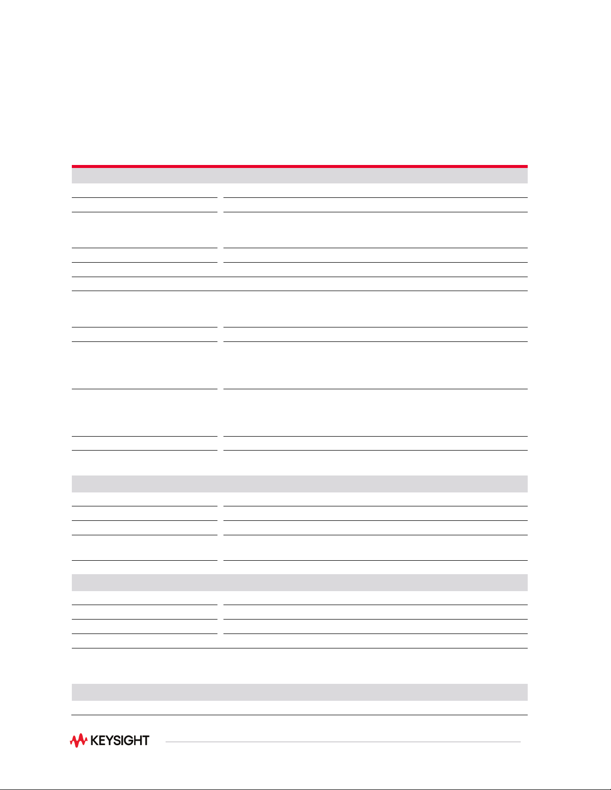
Measurement Characteristics with Optional
Internal DMM
Measurement characteristics
DC voltage
Measurement method
Continuously integrating multi-slope III A-D converter
A-D linearity
0.0002% of reading + 0.0001% of range on 10 V range
Input resistance
100 mV, 1 V, 10 V ranges 100 V,
300 V ranges
Selectable 10 M Ω or > 10,000 M Ω 10 M Ω ± 1%
Input bias current
< 50 pA at 25 °C
Input protection
300 V for Pollution Degree 1 and 100 V for Pollution Degree 2
True RMS AC voltage
Measurement method
AC coupled True RMS—measures the AC component of the input with up
to 300 VDC for Pollution Degree 1 and 100 VDC for Pollution Degree 2 of
bias on any range
Crest factor
Maximum of 5:1 at full scale
Additional crest factor errors (non-
sinewave)
Crest factor 1-2 0.05% of reading
Crest factor 2-3 0.15% of reading
Crest factor 3-4 0.30% of reading
Crest factor 4-5 0.40% of reading
AC filter bandwidth:
Slow
Medium
Fast
3 Hz - 300 kHz
20 Hz - 300 kHz
200 Hz - 300 kHz
Input impedance
1 M Ω ± 2% in parallel with 150 pF
Input protection
Pollution Degree 1: 300 Vrms all ranges
Pollution Degree 2: 100 Vrms all ranges
Resistance
Measurement method
Selectable 4-wire or 2-wire ohms
Current source
Referenced to LO input
Offset compensation
Selectable on 100 Ω, 1k Ω, 10 kΩ ranges
Maximum lead resistance
10% of range per lead for 100 Ω and 1k Ω ranges. 1k Ω on all other
ranges
Input protection
300 V for Pollution Degree 1 and 100 for Pollution Degree 2
Frequency and period
Measurement method
Reciprocal counting technique
Voltage ranges
Same as AC voltage function
Gate time
1 s, 100 ms, or 10 ms
Measurement timeout
Selectable 3 Hz, 20 Hz, 200 Hz LF limit
Measurement consideration (frequency and period): All frequency counters are susceptible to error when
measuring low-voltage, low-frequency signals. Shielding inputs from external noise pickup is critical for
minimizing measurement errors.
DC current
Shunt resistance
5 Ω for 10 mA, 100 mA; 0.1 Ω for 1 A

40
Input protection
1.5 A 250 Vac fuse on 34921A module
True RMS AC current
Measurement method
Direct-coupled to the fuse and shunt. AC coupled True RMS measurement
(measures the ac component only
Shunt resistance
5 Ω for 10 mA; 0.1 Ω for 100 mA, 1 A
Input protection
1.5 A 250 Vac, 50/60 Hz fuse on 34921A module
Thermocouple
Conversion
ITS-90 software compensation
Reference junction type
Internal, fixed, or external
Open thermocouple check
Selectable per channel. Open > 5 kΩ
Thermistor
44004, 44007, 44006 series
RTD
a = 0.00385 (DIN) and a = 0.00392
Measurement noise rejection 60/50 Hz
1
DC CMRR
AC CMMR
140 dB
70 dB
Integration time Normal mode rejection
2
200 plc/3.33 s (4 s)
100 plc/1.67 s (2 s)
20 plc/333 ms (400 ms)
10 plc/167 ms (200 ms)
2 plc/33.3 ms (40 ms)
1 plc/16.7 ms (20 ms)
< 1 plc
105 dB
3
100 dB
3
95 dB
3
90 dB
3
85 dB
60 dB
0 dB
Note:
1. For 1 kΩ unbalance in LO lead
2. For power line frequency ± 0.08%
3. For power line frequency ± 1% use 75 dB or ± 2.5% use 60 dB

41
DC operating characteristics
4
Function
Digits
5
Readings / s
Additional RMS noise error
DCV
7
, DCI, and Resistance
(≤10 kΩ)
6½
6½
5½
5½
4½
4½
0.6 (0.5)
6 (5)
60 (50)
300
600
3000
0% of range
0% of range
0.001% of range
0.001% of range
6
0.01% of range
6
0.1% of range
6
Autozero OFF operation
Following instrument warm-up at calibration temperature ± 1 °C and < 10 minutes, add 0.0002% range
additional error. +5 μV. (For 300 VDC, instead of .0002% of range, need .00066% of range)
Settling considerations
Reading settling times are affected by source impedance, low dielectric absorption characteristics, and input
signal changes.
AC operating characteristics
8
Digits
9
Readings /
AC Filter
ACV, ACI:
6½
6½
6½
6½
7 sec/reading
1
8
10
100
11
Slow (3 Hz)
Medium (20Hz)
Fast (200 Hz)
Fast (200 Hz)
Note:
1. Reading speeds for 60 Hz and (50 Hz) operation; autozero OFF
2. 6½ digits = 22 bits; 5½2 digits = 18 bits; 4½ digits = 15 bits
3. Add 20 μV for DCV, 4 μA for DCI, or 20 mΩ for resistance
4. For 300 VDC, multiply the additional noise error by 3.3
5. Maximum reading rates for 0.01% of AC step additional error; additional settling delay required when input DC
level varies
6. 6½ digits = 22 bits; 5½ digits = 18 bits; 4½ digits = 15 bits
7. For external trigger or remote operation using default settling delay (Delay Auto)
8. Maximum limit with default settling delays defeated