技术资料.pdf - 第14页
14 34980A Ma trix S witch Mo dules The 3498 0A matrix modul es are ful l Crosspo int ma trices that allow yo u to conn ect any r ow to a ny column. This is a co nven ient way t o connec t multi ple test instru ments to m…

13
Multiplexer switch modules
34921A
34922A
34923A
34924A
34925A
Channels/configurations
40 2-wire
20 4-wire
4-current
1.5 A Fused
70 2-wire
35 4-wire
80 1-wire
40 2-wire
20 4-wire
70 2-wire
35 4-wire
80 1-wire
40 2-wire
20 4-wire
Switch type
Armature latching
Armature latching
Reed
Reed
Optically isolated FET
Input characteristics (per channel)
Max volts
± 300 V
1, 13
± 300 V
1, 13
± 150 V peak
2, 14
± 150 V peak
2, 14
± 80 V peak
2
Max current
(DC, AC RMS)
Switch current
1 A 1 A 0.5 A
5
/ 0.05 A
11
0.5 A
5
/ 0.05 A
11
0.02 A
8
Carry current
2 A
2 A
1.5 A
5
/ 0.05 A
11
1.5 A
5
/ 0.05 A
11
Power (VA)
6
60 VA
60 VA
10 VA
10 VA
1.6 VA
Volt-Hertz limit
10^8
10^8
10^8
10^8
10^7
Initial closed channel res
3
< 1.5 Ω
12
< 1.5 Ω
12
< 1.5 Ω
5
/200
11
nominal
< 1.5 Ω
5
/200
11
Nominal
< 700 Ω
11
General specifications
Offset voltage
3
< 3 μV < 3 μV
< 50 μV
< 100 uV 1-wire
< 50 uV < 3 μV
DC Isolation (ch-ch, ch-earth)
> 10 GΩ
> 10 GΩ
> 10 GΩ >
10 GΩ
> 10 GΩ
Leakage current
3
N/A
N/A
N/A
N/A
20 nA
9
T/C cold junction accuracy
3, 10
< 1°C N/A N/A N/A N/A
AC characteristics
Bandwidth at terminal block
4
45 MHz 25 MHz
45 MHz
5
/4 MHz
10 MHz 1-wire
25 MHz
5
/4 MHz
11
1 MHz
Crosstalk at terminal block (ch-ch)
4
300 kHz
- 75 dB - 75 dB - 75 dB - 75 dB
Not recommended for
RF signal switching
1 MHz
20 MHz
45 MHz
- 75 dB
- 50 dB
- 40 dB
- 75 dB
- 50 dB
- 75 dB
- 50 dB
- 40 dB
- 70 dB
- 45 dB
Capacitance at terminal block
HI-LO
LO – earth
150 pF
150 pF
250 pF
200 pF
130 pF
120 pF
200 pF
170 pF
100 pF
300 pF (600 pF 1-wire)
General Characteristics
Relay life, typical
No-load
10 V, 100 mA
Rated load
100 M
10 M
100 k
100 M
10 M
100 k
1000 M
10 M
10 k
1000 M
10 M
10 k
Unlimited within banks
Scanning speeds
7
100 ch/sec
100 ch/sec
500 ch/sec
500 ch/sec
1000 ch/sec
Open/ close time, typical
4 ms/4 ms
4 ms/4 ms
0.5 ms/0.5 ms
0.5 ms/0.5 ms
0.25 ms/0.25 ms
Analog bus backplane
Yes
Yes
Yes
Yes
Yes
Notes:
1. DC or AC RMS voltage, channel-to-channel or channel-to-earth
2. Peak voltage, channel-to-channel or channel-to-earth
3. Into analog bus. System errors are included in the internal DMM measurement accuracy specifications
4. 50 Ω source, 50 Ω load, differential measurements verified with 4-port network analyzer (Sdd21)
5. With input resistors bypassed. Bypassing resistors will reduce the lifetime of relays. See the rated load relay life
characteristics.
6. Limited to 6 W of channel resistance power loss per module
7. Speeds are for 2-wire ohms or DCV, 4 1/2 digits, delay 0, display off, autozero off, and within the bank
8. DC or peak AC current
9. Ambient temperature < 30°C
10. Includes 0.5°C temperature reference sensor and 0.5°C terminal block isothermal gradient error, measured under
worst-case loading of the mainframe; see User’s Guide for information on supported external reference sensors
11. With input protection resistors: 2 x 100 Ω ±5%; 0.5W; TC = ±200 ppm/°C. The series resistance of the 34923/24/25
limits the use of the 100 Ω range.
12. Channel resistance is typically < 1.5 Ω but can go as high as 50 Ω when a channel is used in measurement
applications with < 10 mA load current. Increased relay channel resistance for measurements with load currents
below 10 mA can occur on cards that have been out of service or following relay inactivity for periods of greater
than 1 week. Switching relays for 2K cycles prior to use may reduce the variation in channel resistance. Applies to
the 34921A and 34922A. Keysight recommends the use of 4-wire Ohms for resistance measurements. For high
accuracy voltage measurements, select the DMM input resistance setting of >10 G ohms to minimize the impact of
relay contact resistance.
13. Pollution Degree 1 ±300Vrms or VDC; Pollution Degree 2 ±100Vrms or VDC
14. Pollution Degree 1 ±150Vpeak; Pollution Degree 2 ±100Vpeak
14
34980A Matrix Switch Modules
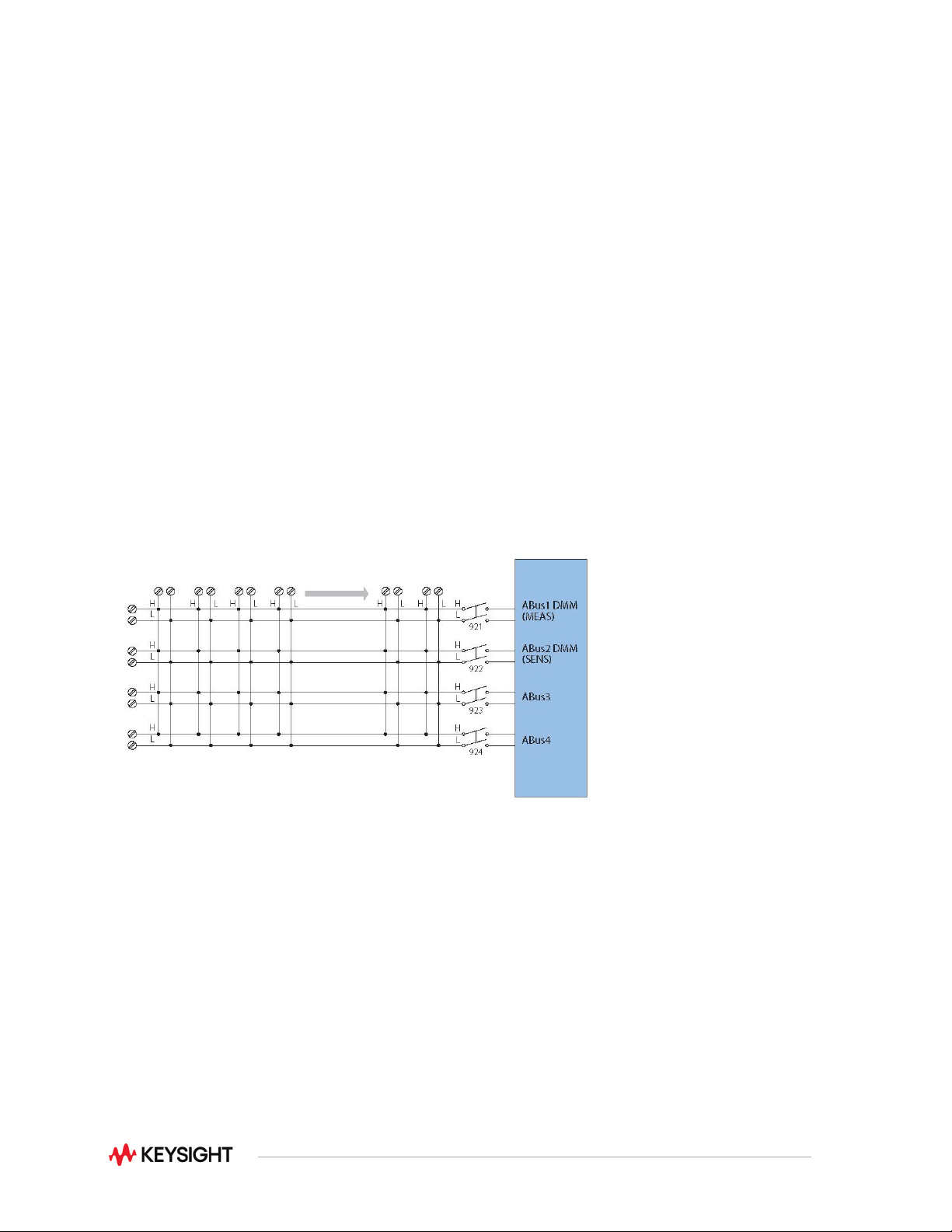
The 34980A matrix modules are full Crosspoint matrices that allow you to connect any row to any column.
This is a convenient way to connect multiple test instruments to multiple points on a device under test.
Choose from the following features:
•
Latching armature relays— Max 300 Vrms or DC, 1 A
•
High-speed reed relays— Max 150 Vpeak, 0.5 A
•
Configurable dual 4x8, dual 4x16, or quad 4x32 modules
•
Single-wire configuration (34933A or 34934A)
•
High-density matrix with automatic surge protection and row disconnects for flexible measurements
(34934A)
•
Analog bus expandable rows to create larger matrices
•
(34931A, 32A, 33A)
•
Connections via standard 50 or 78-pin D-sub cables or detachable terminal block
Each cross-point in the matrix switch has two wires—a high and a low for the measurement. Or, if you
prefer, the 34933A and 34934A can be configured as a single-wire matrix, increasing the number of
channels.
Figure 5. 34932A dual 4x16 armature matrix
15
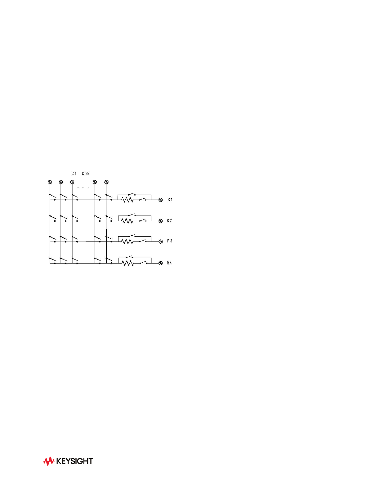
The 34933A also has in-rush resistors on each column for added protection. The 34934A also has in-rush
protection resistors but also has an automatic bypass switch for flexibility in making low-level
measurements. Row disconnect switches also reduce the capacitance loading when combining modules
to create larger matrices.
Multiple matrix modules can be combined through the analog bus or the row expansion kit (34934A only)
to create a larger matrix. The matrix can then be connected to the internal DMM for easy measurements.
Combine your matrix with a multiplexer switch to achieve the desired switching topology and get a lower-
cost solution with better specifications. All the matrix switches include a relay counter to help predict when
relays need to be replaced. Use the sequencing feature to easily change between different cross-point
setups.
NOTE: The 34933A and 34934A have 100-ohm input protection resistors to limit current and protect the
reed relays.
Figure 6. 34934A quad 4x32 matrix (1 of 4 matrices shown)