4X4CEIM.pdf - 第35页
Page 1-11 INST ALLA TION 1 2) Machine placement Place the machine along the reference line. Adjust the machine position so that the board is smoothly transferred between the previous and the next processes. (Direction an…
Page 1-10
1-2 Installation Procedure
NOTICE
Machine installation is conducted by experts.
Here, the outline of the procedure is described.
For rearranging the machine, make contact with the service department.
1-2-1 CM301-DU Installation Procedure
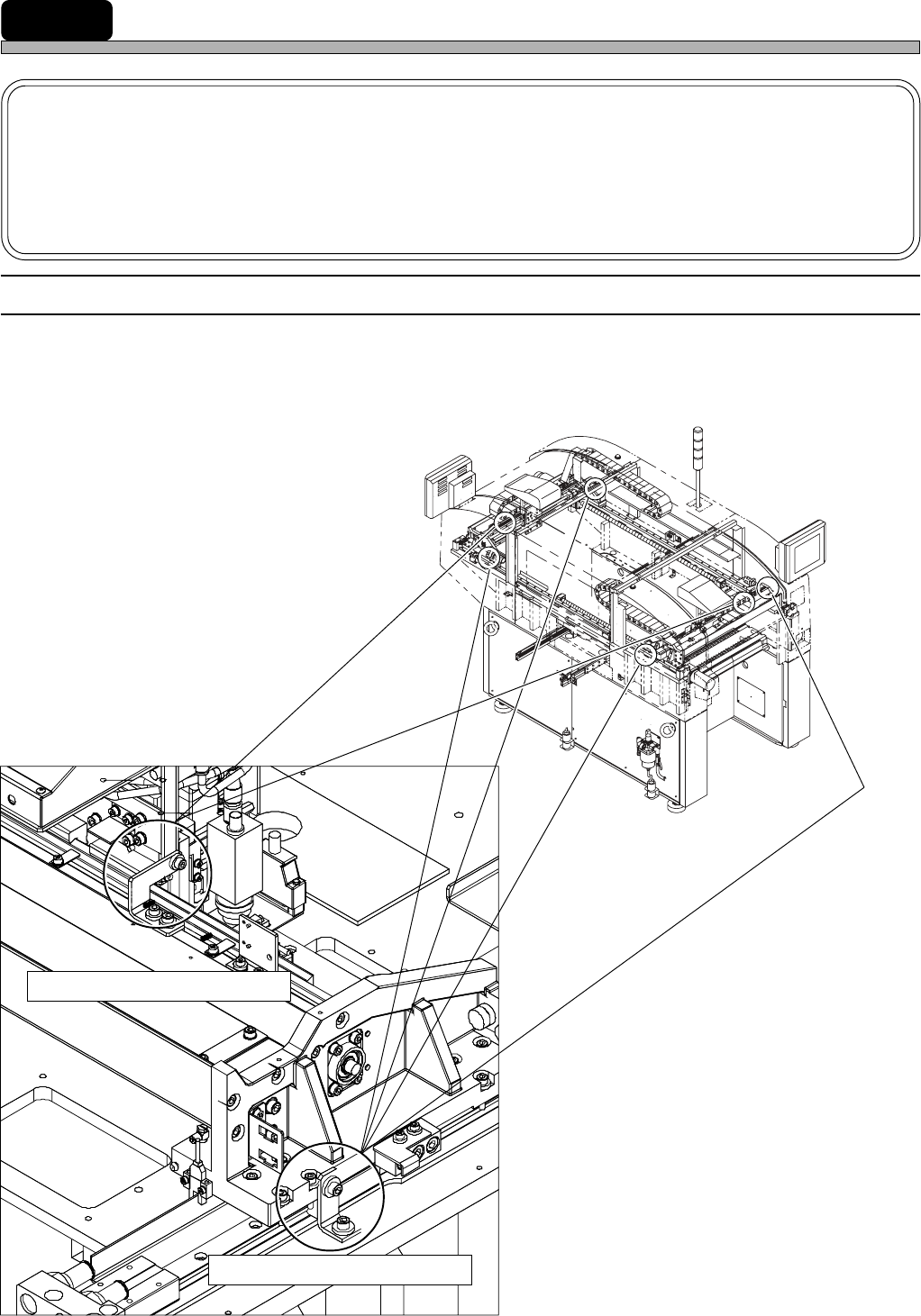
1) Machine transport state
During the machine transport, X-axis and Y-axis and are fixed with the fixing brackets (red) to
prevent removing.
4X4C-E-IMA01-A01-00
4X4C-012E
4H4C-AK00
X-axis fixing brackets (2 points)
Y-axis fixing brackets (4 points)
Page 1-11
INSTALLATION
1
2) Machine placement
Place the machine along the reference line. Adjust the machine position so that the board is
smoothly transferred between the previous and the next processes. (Direction and height of
transfer)
3) Removing the fixing bracket (red)
Remove all brackets (red). Keep the removed brackets.
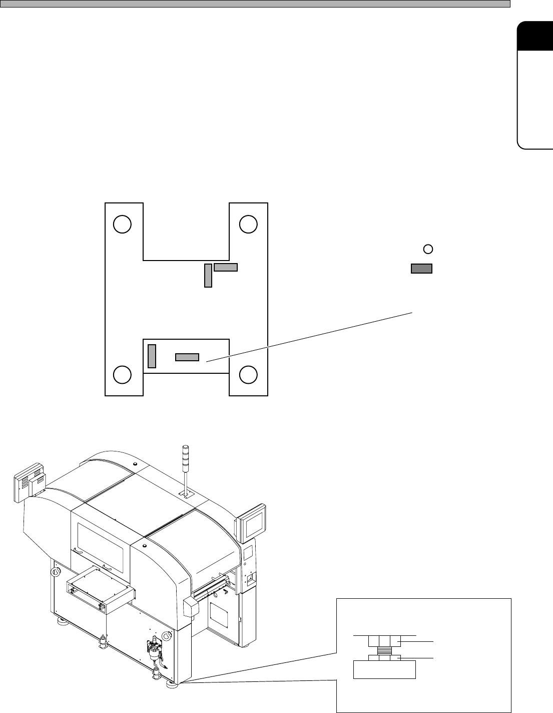
4) Setting the accurate level
Install the level (0.02 mm / m / div) to the position described below.
Adjust it so that it gets less than a scale (0.02 mm / m) by using the adjustment bolt.
After adjustment tighten the locking nut.
Locking nut
Installing Procedure
4X4C-E-IMA01-A01-00
Adjustment bolt
Level pad
: Level pad
: Installing
position
of the level
1B4C-840E
Tape Feeder Base
4X4C-AA00
Page 1-12
5) Connecting the surrounding devices
Install the status Indicator according to the procedure of 1-3.
In case of the line specification, connect a signal cable as 1-1-6.
6) Connecting the power source and air source
Connect the primary power source and the primary air source.
7) Adjust the air pressure
Adjust the regulator so that the secondary air pressure is 0.49 MPa.
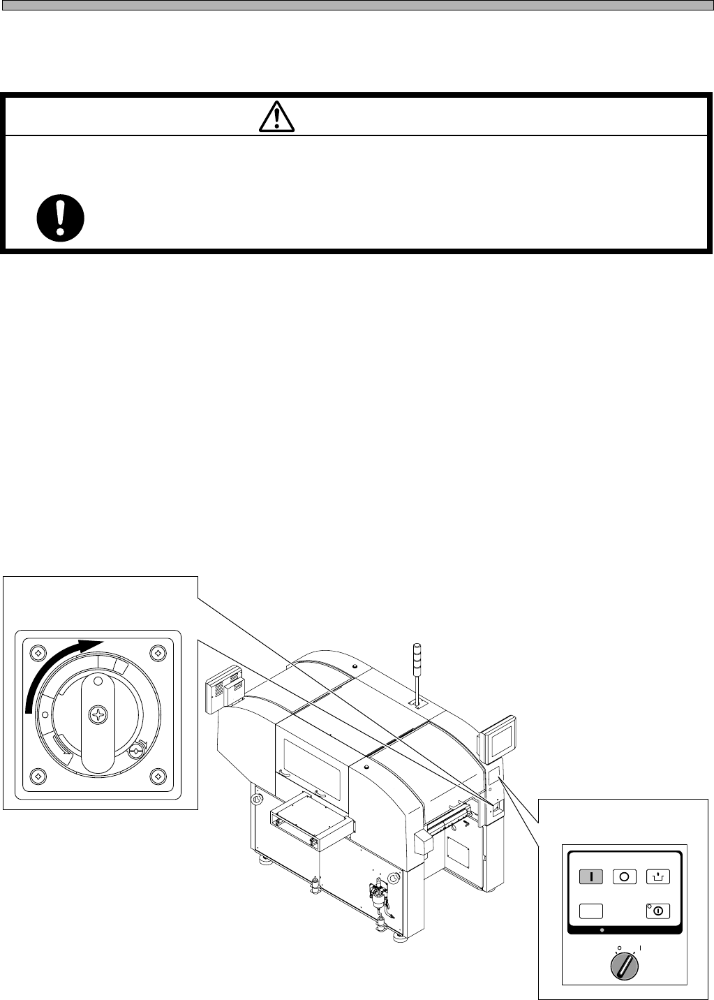
8) Power supply
(1)Turn the main power switch ON.
(2)Turn the servo select switch ON.
Installing Procedure
4X4C-E-IMA01-A01-00
(2) Servo select switch
M 92E
POWER AND AIR SOURCES SHOULD BE CONNECTED AT THE LAST OF
INSTALLING OPERATION.
If they are connected earlier, you may get an electric shock or injured.
WARNING
R
E
L
E
A
S
E
T
R
I
P
O
F
F
O
N
R
E
S
E
T
(1) Main power switch
OFF ( )
ON ( )
SERVO
STOP
UNLOCK
STEP
START
SELECT
KEY LOCK
KEY LOCK
4X4C-AA00