4X4CEIM.pdf - 第37页
Page 1-13 INST ALLA TION 1 1-2-2 DT40T -40U Installation Procedure Coupling DT40T -40U to CM301 1) The T ransport State of the Machine During the machine transport, the fixing brackets (red) fix the lift shafts and the d…
Page 1-12
5) Connecting the surrounding devices
Install the status Indicator according to the procedure of 1-3.
In case of the line specification, connect a signal cable as 1-1-6.
6) Connecting the power source and air source
Connect the primary power source and the primary air source.
7) Adjust the air pressure
Adjust the regulator so that the secondary air pressure is 0.49 MPa.
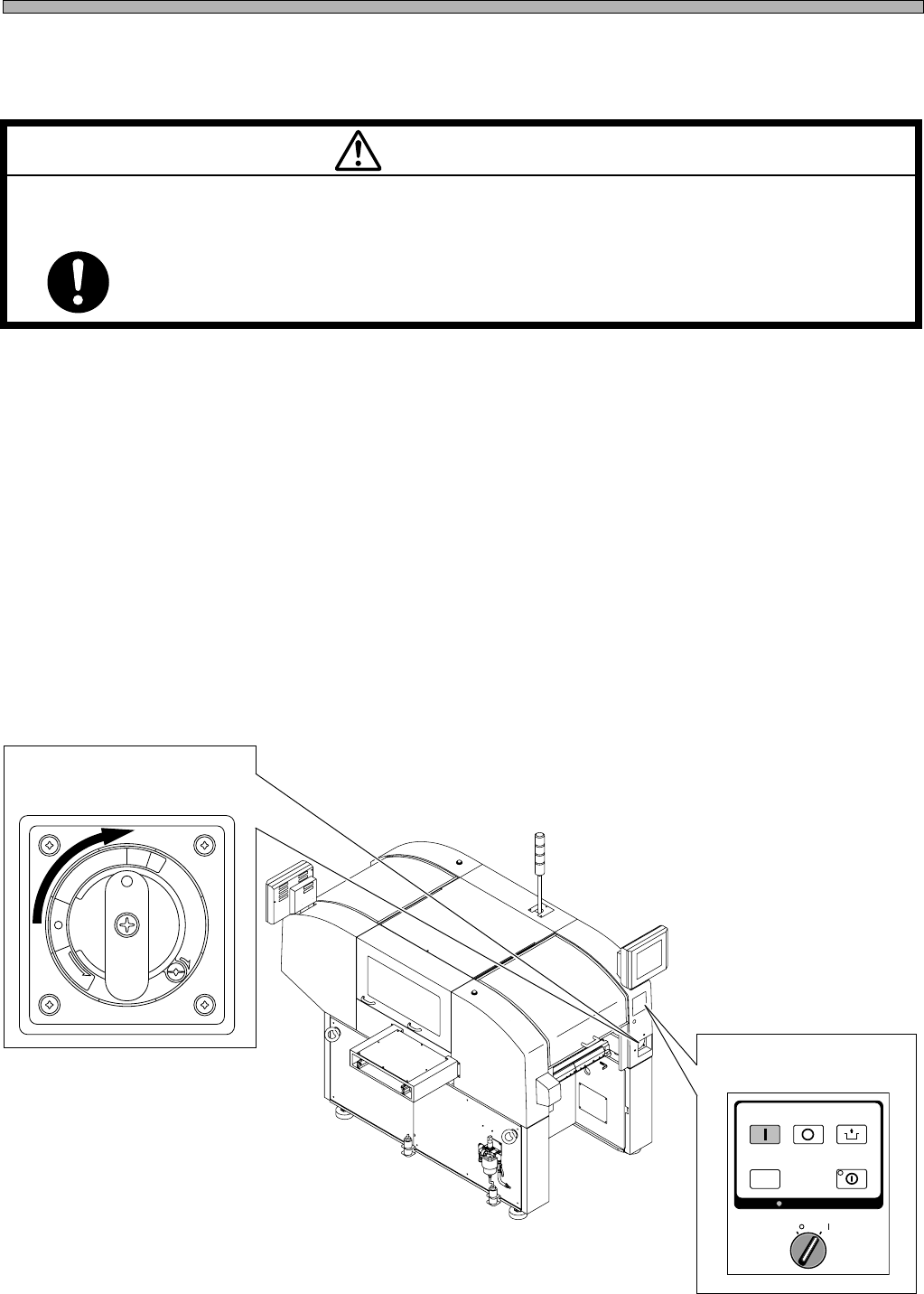
8) Power supply
(1)Turn the main power switch ON.
(2)Turn the servo select switch ON.
Installing Procedure
4X4C-E-IMA01-A01-00
(2) Servo select switch
M 92E
POWER AND AIR SOURCES SHOULD BE CONNECTED AT THE LAST OF
INSTALLING OPERATION.
If they are connected earlier, you may get an electric shock or injured.
WARNING
R
E
L
E
A
S
E
T
R
I
P
O
F
F
O
N
R
E
S
E
T
(1) Main power switch
OFF ( )
ON ( )
SERVO
STOP
UNLOCK
STEP
START
SELECT
KEY LOCK
KEY LOCK
4X4C-AA00
Page 1-13
INSTALLATION
1
1-2-2 DT40T-40U Installation Procedure
Coupling DT40T-40U to CM301
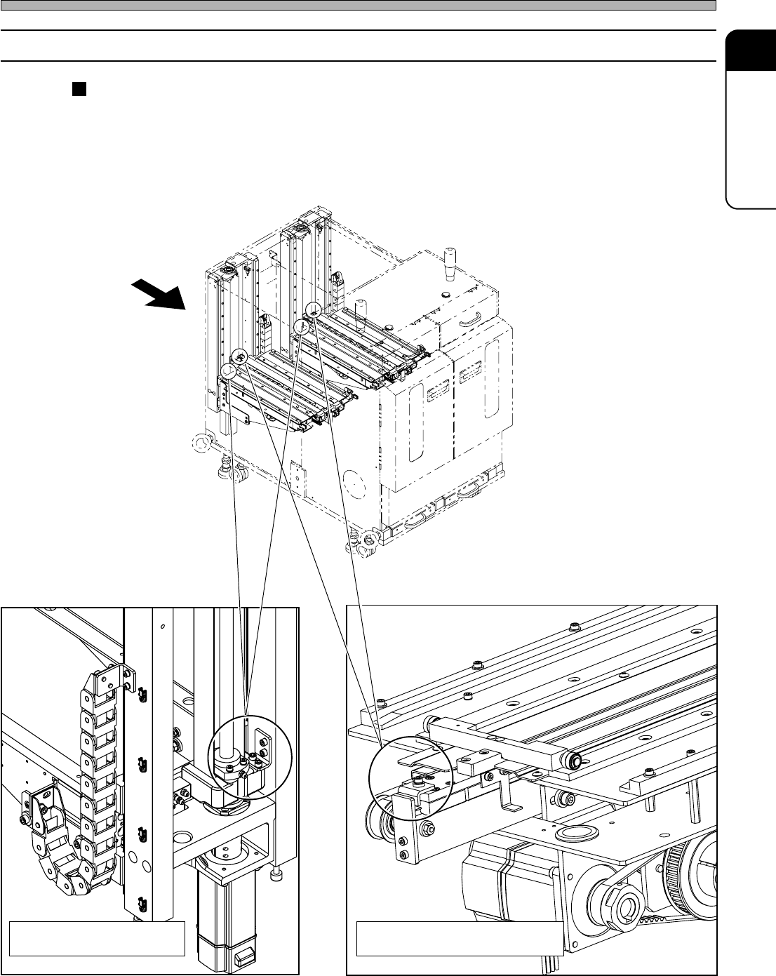
1) The Transport State of the Machine
During the machine transport, the fixing brackets (red) fix
the lift shafts and the drawers not to move.
4X4C-E-IMA01-A01-00
1.Multi-step Tray Lift Fixing
Bracket (Two in All)
2. Multi-step Tray Drawer Fixing
Bracket (Two in All)
View seen from A View seen from A
A
4M4C-AG00
4X4C-010E
4X4C-011E
Page 1-14
2) Removing the Fixing Brackets (Red)
Remove all the fixing brackets. Keep the removed brackets.
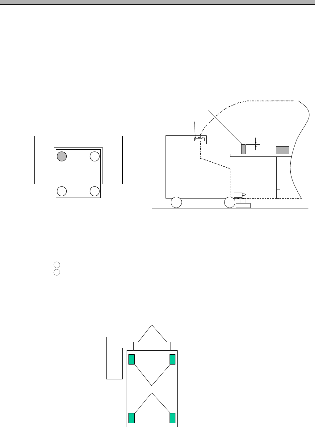
3) Height Adjustment and Leveling
Level the rear-side height with the reference height of the CM301.
[1] Adjust the adjuster bolt of the caster A so that the height will be ± 1 mm or under against the
heiight check post. After adjusted, fix the bolt by tightening the lock nut.
[2] While checking the built-in level, Adjust the adjuster bolts of the caster B, C and D so that the
height will be ± 0.3 mm/m or under.
4) Inserting DT40T-40U into the CM301
[1] Insert the DT40T into the CM301.
[2] Check if they are level.
1
Is the value of the level ± 0.3 mm/m or under?
2
Isn’t the caster A or B floating?
If floating, the coupling pins have run up onto the machine. Pull the DT40T out of the CM301,
and insert it again.
[3] When the above check points are cleared, fix the adjuster bolts of the caster B, C and D by
tightening the lock nuts.
4X4C-E-IMA01-A01-00
4X4C-006E
4X4C-003E
4X4C-004E
Height Check Post
Level
± 0.3 mm/m or under
± 1 mm or under
Coupling Pin
Caster
A
C
B
D
A
C
B
D