4X4CEIM.pdf - 第42页
Page 1-18 4X4C-E-IMA01-A01-00 1-3 Assembling Procedure of Surrounding Devices 1-3-1 Setting the Status Indicator 1) Install the indicator to the main body . • Fix it by tightening the hexagonal nuts from the inside of th…
Page 1-16
4X4C-E-IMA01-A01-00
Final Check of Leveling
After the DT40T-40U is fixed to the CM301, finally check leveling by performing the following
procedure.
1) Turning ON the Power of the CM301
Turn ON the power switch of the CM301. At the same time, the power of the DT40T will be turned
ON.
2) Traveling the Drawer Shaft to the Supply Area Height
Perform the following operations at the “Machine Adjustment” screen in the serviceman mode.
NOTICE
Users cannot perform operations in the serviceman mode. (The key disk is
required.)Entrust these operations to a serviceman.
[1] Perform “Returning to Origin”.
[2] Make sure the supply shutter is “open”
by a visual inspection.
[3] Enter the “Shaft Traveling” mode.
[4] Press AR .
[5] Press TLA .
[6] Make sure the “Current Position” is ± 3.
• If Mit is not within ± 3, perform “Returning to
Origin”.
[7] Press Distance , and input “422”.
[8] Press Z↑ .
• The lift shaft will be raised up.
[9] Press TLB .
[10] Perform steps [6] to [8].
• The lift shaft will be raised up, in the same way
as the A side.
Traveling to
the supply position
4X4C-007E

Page 1-17
INSTALLATION
1
4X4C-E-IMA01-A01-00
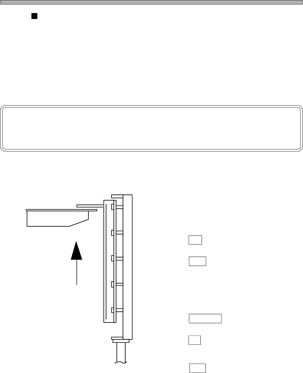
3)
Checking the Difference in Level between the Drawer Shaft ResinGuide and the
Fixed Guide at the CM301 side
Make sure the pallet drawn out from the drawer is not interfered with the fixed guide at the DT40T.
• There are four checkpoints. Each one is on right and left for each side (A and B).
∗ If interfered, perform leveling again.
4) Performing the Tray Pickup Position Teaching
Teach the “tray pickup position” at the machine parameters teaching.
• See the Maintenance Manual for how to operate
4X4C-008E
4X4C-009E
Drawer Guide of the Main Body
Pallet
Not Interfered
Interfered
OK NG
Page 1-18
4X4C-E-IMA01-A01-00
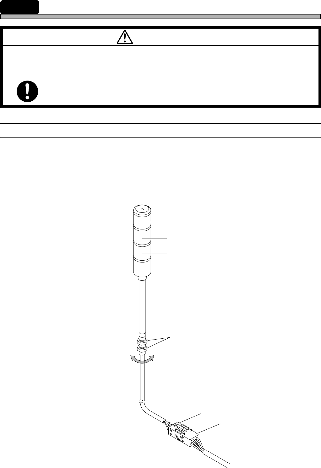
1-3 Assembling Procedure of Surrounding Devices
1-3-1 Setting the Status Indicator
1) Install the indicator to the main body.
• Fix it by tightening the hexagonal nuts from the inside of the cover.
2) Connect the indicator signal cables to the indicator connection terminal.
• Insert the plug set at the end of the cable to the socket on the main body, with a hook.
Socket
Plug
Hexagonal nuts
Red
Yellow
Green
M 93E
BEFORE INSTALLATION OF ATTACHED EQUIPMENT, MAKE SURE THAT
POWER AND AIR SOURCES ARE NOT CONNECTED WITH THE BODY OF
MACHINE.
If they are connected, you may get an electric shock or injured.
WARNING
183C-IL009