Infinity DI.pdf - 第20页
INFINITY TECHNI CAL REFEREN CE SEQUEN CES Chapter Issu e 4 Aug 01 Infinity Dual Imag e Manual 1.15 SEQUENCES Home Se quence The screen change mechanism only carries out a homing sequence when the machine initi alizes. Th…
1.14 Infinity Dual Image Manual Chapter Issue 4 Aug 01
INFINITY
TECHNICAL REFERENCE
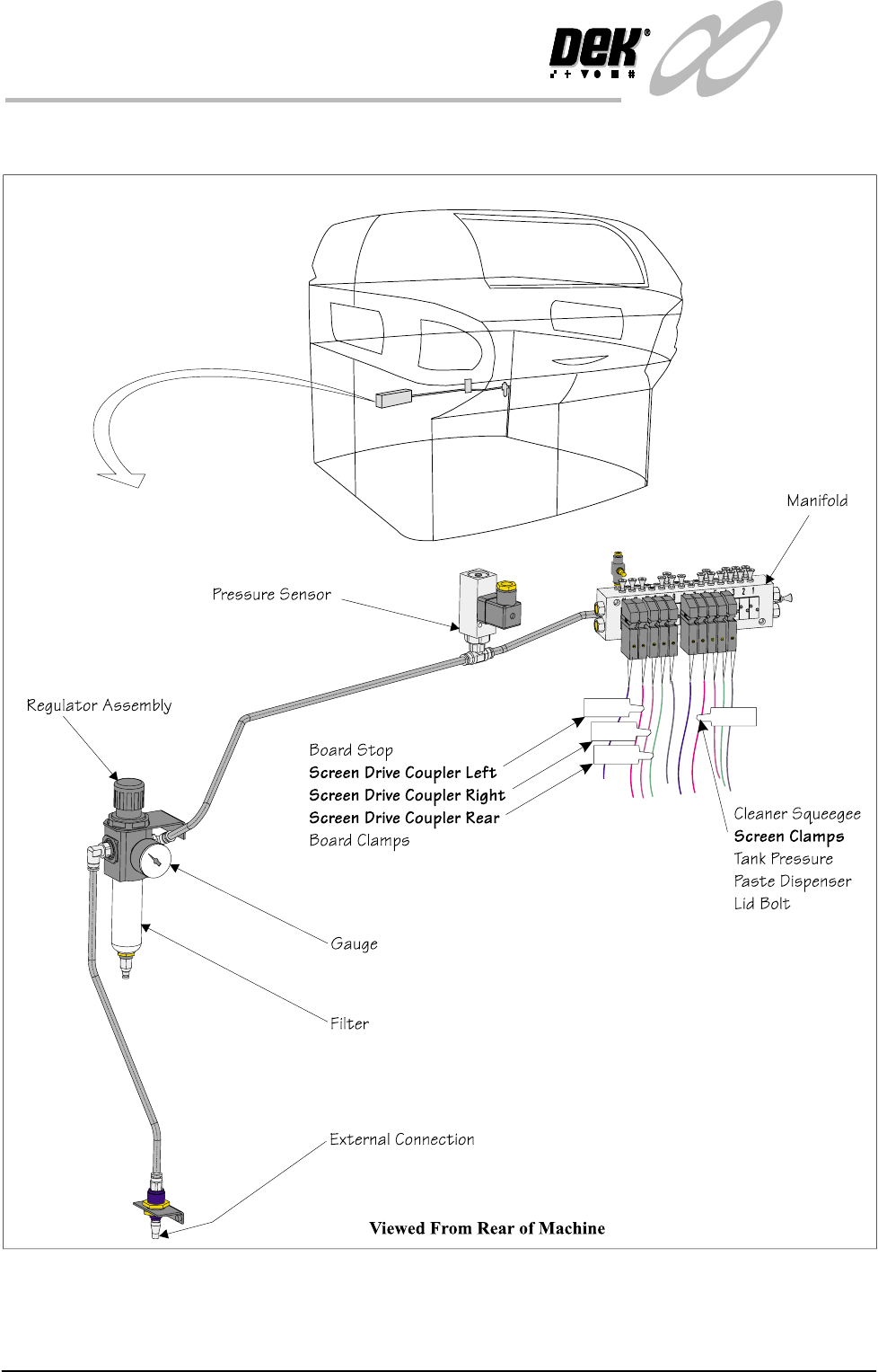
PNEUMATIC OVERVIEW
PNEUMATIC OVERVIEW
Figure 1-10 Pneumatics

INFINITY
TECHNICAL REFERENCE
SEQUENCES
Chapter Issue 4 Aug 01 Infinity Dual Image Manual 1.15
SEQUENCES
Home Sequence The screen change mechanism only carries out a homing sequence when the
machine initializes. The home sequence occurs when the system power is
applied to the machine or, when exiting the MMI Diagnostics page.
The homing sequence is as follows:
1. The screen load motor drives the mechanism toward the front of the machine.
2. The screen load motor stops when the home sensor detects the vane.
3. The screen load motor reverses direction and drives the mechanism toward
the rear of the machine.
4. The screen load motor stops the instant the sensor clears the home vane. This
is the home position.
5. The motor drives 5000 steps (343.6mm) to the rear of the machine. This is
the zero datum position, from which all screen locations are calculated.
Screen Unload If Change Screen is selected, the software interrogates the screen at front, centre
and rear sensors. the screen automatically unloads as follows:
1. The screen clamps are de-energized.
2. The drive couplings are energized and the mechanism drives the screen
toward the front.
3. The screen stops when it is detected by the screen in transit ‘front’ sensor.
4. The operator is prompted to remove the screen.
Screen Load (Single
Image Mode)
If Change Screen is selected, the software interrogates the screen at front, centre
and rear sensors. If no screen is detected the software prompts the user to insert
a screen. Once the screen has been inserted and Change Screen selected,
automatic screen load and registration takes place. An automatic screen load
sequence also takes place if the machine is initialized with a screen in the chase.
The screen load sequence is as follows:
1. The screen drive unit drives towards the front of the machine until it reaches
home position (it does not actually home).
2. The front and rear couplings are energized and grip the screen.
3. The screen is driven into the chase until it is detected by the screen at 'rear'
sensor
4. The screen is driven forward until it clears the sensor.
5. The drive couplings are de-energized.
6. The screen drive unit drives to the rear of the machine.
7. The two rear drive couplings are energized behind the screen.
8. The screen drive unit moves forward and positions the screen
9. The front right hand drive coupling is energized, pushing the screen against
the left chase rail.
10. The screen clamps are energized. The drive couplings are de-energized.
1.16 Infinity Dual Image Manual Chapter Issue 4 Aug 01
INFINITY
TECHNICAL REFERENCE
SEQUENCES
Screen Shuttle Sequence (Auto Load) - Image at the Front
Automatic Load - Bar Code Reader Option (BCR)
Ensure that the correct boards for printing are loaded into the feeder.
1. Turn the printing machine on and initialize.
2. Set up the product files, set the tooling and load the screen (The chase
actuators disengage).
3. Select Auto from the mode option on the status page.
4. Select Run.
5. The screen shuttle actuators move the screen in the chase until the sensor at
the rear detects the presence of the screen.
6. The screen shuttle actuators (rear) engage the screen at the rear, the actuators
are coupled and the front actuators engage to grip the screen. The screen is
moved forward
7. The shuttle actuators disengage the screen and move forward to allow the
rear actuators to engage in the slot to clamp the screen.
8. The front left actuator releases and the right hand actuators fully engage to
allow the screen to be pushed to the left.
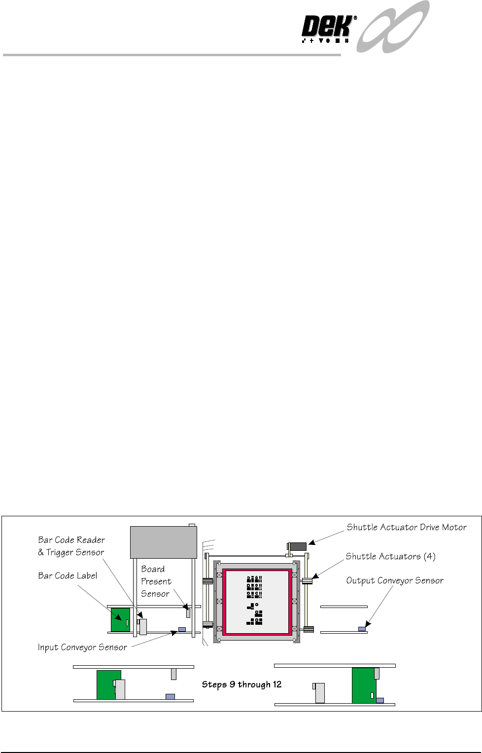
9. The first board in the batch is fed to the bar code reader. The reader has a
sensor mounted before it that detects the board, this acts as a trigger to bring
the BCR on.
10.The label is read and the product file is compared to enable the machine to
be set up for the product.
11.The board continues travel on the inroad conveyor until it reaches the
conveyor sensor where it stops.
12.The board present sensor confirms that the board has arrived at the correct
location.
13.As the board details have been confirmed by the BCR, the machine starts the
shuttle action of the screen.
Figure 1-11 Load Sequence Front Image - Bar Code Reader Option