Infinity DI.pdf - 第39页
1.34 Infinity Dual Imag e Manual Chapter Issue 4 Aug 01 INFINITY TECHNIC AL RE FERENCE ADJUS TMENT S AND SET TINGS Sensor Frame The sensor frame can be hei ght adjusted, t his optimizes the reading ca pability of the sen…
INFINITY
TECHNICAL REFERENCE
ADJUSTMENTS AND SETTINGS
Chapter Issue 4 Aug 01 Infinity Dual Image Manual 1.33
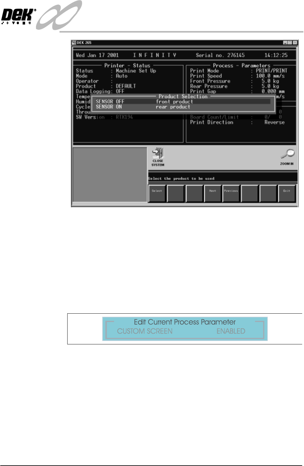
Figure 1-29 Select Product Sensor
NOTE
Sensor Off and Sensor On are names given to the product sensor, this
distinguishes it when selecting for example:- The Front Product.
After selection the Load Data page (if in load data mode) or Edit Data (if in
edit data mode) is displayed. The product can be loaded or parameters edited
in the standard way.
7. Before dual image can be operated, in Edit Process Parameters scroll down
the page until Custom Screen is displayed. Select Enabled.
Figure 1-30 Set Custom Screen to Enabled
1.34 Infinity Dual Image Manual Chapter Issue 4 Aug 01
INFINITY
TECHNICAL REFERENCE
ADJUSTMENTS AND SETTINGS
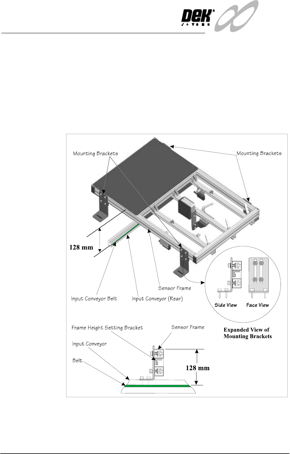
Sensor Frame The sensor frame can be height adjusted, this optimizes the reading capability
of the sensors. Setting the height as shown is good for all sensor types.
Frame Height
Setting
The mounting brackets are secured in the ‘T’ slots of the sensor frame and onto
the conveyor rails. The height of the frame should be set to the dimension shown
(128mm from the top of the conveyor belt to the top of the frame section). The
smaller bracket at the rear of the mounting bracket (Frame Height Setting
Bracket) maintains this height adjustment, it is set by sliding it in its slot up to
the underside of the sensor frame where it is locked. Once set, the brackets may
be moved to a new location (e.g., where rail width needs adjusting) without the
need to reset the height. Once the height has been set, the correct focus for the
sensors is maintained
Figure 1-31 Sensor Frame Height Adjustment
INFINITY
TECHNICAL REFERENCE
ADJUSTMENTS AND SETTINGS
Chapter Issue 4 Aug 01 Infinity Dual Image Manual 1.35
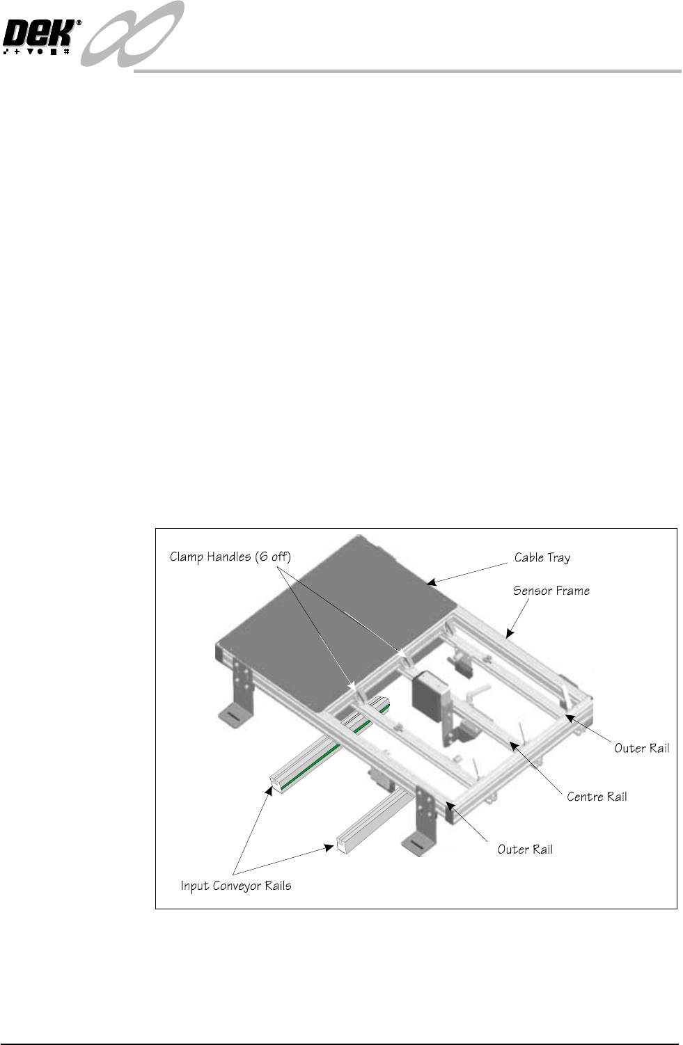
Configuring the Sensor Frame for the Upline Conveyor
The sensor frame is supplied to the customer requirements. If the process is
altered e.g., the printing machine is repositioned and the input conveyor is
changed-over, then the sensor positions need to be ‘mirrored’ on the frame.
To reconfigure the frame for use on the opposite input conveyor, the sensors all
need to be ‘mirrored’.
1. The clamp handles can be lifted against a spring and repositioned.
2. Remove the centre rail. Slacken the handles at both ends and slide the rail
out of the clamps.
3. Rotate the rail by 180
0
so that the bar code reader is facing in the opposite
direction. Refit the rail.
4. Remove the tie wrap and reverse the cable loop so that the reader can be
positioned along the rail. Re tie wrap to secure the cable.
5. Remove the rail with the ‘Board Present Sensor’ fitted. Rotate it and move it
to the opposite side of the centre rail, feed the cable under the centre rail, refit
the rail.
6. Relay the cables in the tray so that the cables do not bind and they allow
freedom of movement.
7. If the ‘Product Sensor’ option is fitted then complete Step 3 the same as for
the bar code option.
Figure 1-32 Reconfiguring the Frame