Infinity DI.pdf - 第41页
1.36 Infinity Dual Imag e Manual Chapter Issue 4 Aug 01 INFINITY TECHNIC AL RE FERENCE ADJUS TMENT S AND SET TINGS Fitting the Frame to the Con vey or If the frame has been moved from its original posit ion to the opposi…
INFINITY
TECHNICAL REFERENCE
ADJUSTMENTS AND SETTINGS
Chapter Issue 4 Aug 01 Infinity Dual Image Manual 1.35
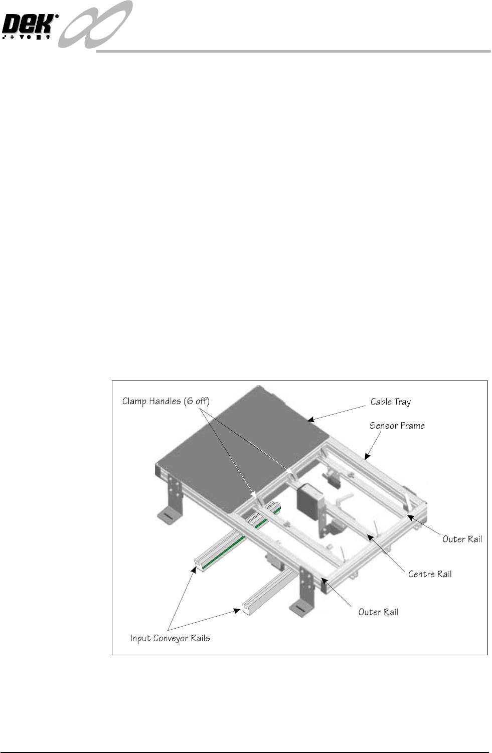
Configuring the Sensor Frame for the Upline Conveyor
The sensor frame is supplied to the customer requirements. If the process is
altered e.g., the printing machine is repositioned and the input conveyor is
changed-over, then the sensor positions need to be ‘mirrored’ on the frame.
To reconfigure the frame for use on the opposite input conveyor, the sensors all
need to be ‘mirrored’.
1. The clamp handles can be lifted against a spring and repositioned.
2. Remove the centre rail. Slacken the handles at both ends and slide the rail
out of the clamps.
3. Rotate the rail by 180
0
so that the bar code reader is facing in the opposite
direction. Refit the rail.
4. Remove the tie wrap and reverse the cable loop so that the reader can be
positioned along the rail. Re tie wrap to secure the cable.
5. Remove the rail with the ‘Board Present Sensor’ fitted. Rotate it and move it
to the opposite side of the centre rail, feed the cable under the centre rail, refit
the rail.
6. Relay the cables in the tray so that the cables do not bind and they allow
freedom of movement.
7. If the ‘Product Sensor’ option is fitted then complete Step 3 the same as for
the bar code option.
Figure 1-32 Reconfiguring the Frame
1.36 Infinity Dual Image Manual Chapter Issue 4 Aug 01
INFINITY
TECHNICAL REFERENCE
ADJUSTMENTS AND SETTINGS
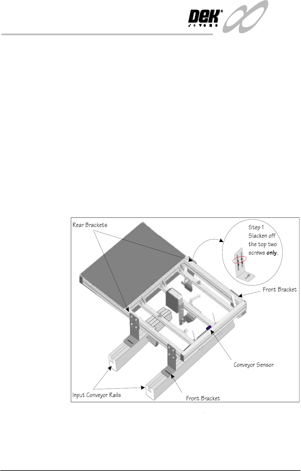
Fitting the Frame
to the Conveyor
If the frame has been moved from its original position to the opposite input
conveyor, it needs to be fitted to the input conveyor framework.
1. Slacken the top two screws holding the rear brackets.
2. Place the frame on the conveyor with the front brackets resting on the front
conveyor rail.
3. Roughly position the rear corner brackets so that they rest on the rear
conveyor rail. Make sure that the corner brackets do not interfere with board
transport.
4. Position the frame left to right such that the ‘Board Present Sensor’ is
roughly aligned with the conveyor sensor.
5. Fit the screws and nuts to loosely hold the four corner brackets to the
conveyor ‘T’ slots
6. Check the frame to conveyor height setting - 128 mm from the top of the
frame to the top of the conveyor belt. If necessary slacken off the lower two
screws on each of the corner brackets (Step 1 shows the top two screws only,
slackened off) and adjust as necessary
7. Fit the cables from the rear service panel to the frame. Bar code reader
connects to 6SK17 the ‘Board Present Sensor’ connects to 6SK21 while the
‘Product Sensor’ connects to 6SK20. Tie wrap the cables to secure.
Figure 1-33 Fitting the Frame to the Machine

INFINITY
TECHNICAL REFERENCE
CALIBRATION
Chapter Issue 4 Aug 01 Infinity Dual Image Manual 1.37
CALIBRATION For calibration of individual modules, reference should be made to the relevant
chapter of the Infinity Technical Reference Manual.