Infinity DI.pdf - 第54页
Chapter Issu e 3 Jan 01 Infinity Dual Imag e Manual 2.7 INFINITY OPERATOR SET U P Change T ooling F or informa tion on tooling options s ee the T ooling section of this chapter . NO TE DEK r ecomme nd that only magnetic …
2.6 Infinity Dual Image Manual Chapter Issue 3 Jan 01
INFINITY
OPERATOR
SET UP
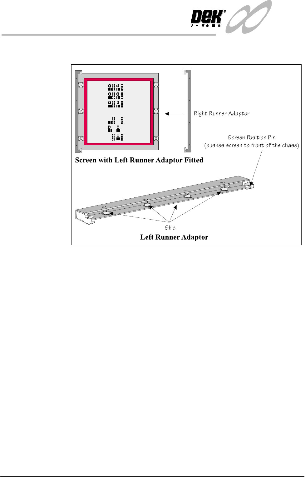
Change Screen Where required fit the runner adaptors to the left and right side of the dual image
screen (if they are not already fitted).
Figure 2-2 Fit the Runner Adaptors to the Screen
6. Select Change Screen (F5).
7. When prompted, lift the front cover and remove the screen that is fitted.
8. Load the dual image screen into the printer.
9. Close the printhead cover.
10.Press the System button.
The screen loads into the machine but does not load to either Product A or
Product B locations.

Chapter Issue 3 Jan 01 Infinity Dual Image Manual 2.7
INFINITY
OPERATOR
SET UP
Change Tooling For information on tooling options see the Tooling section of this chapter.
NOTE
DEK recommend that only magnetic tooling pins are changed by the operator.
Other tooling options may require board configuration files to be altered.
11.Select Change Tooling (F6).
12.Select Head (F2).
13.Raise the head using the two button control.
14.Fit the head prop.
15.Place the tooling in the correct location for the products to be printed
NOTE
The use of the plural in products above is deliberate as it is a requirement for
both product A and product B tooling to be placed or adjusted at this time. For
details see the ‘Tooling’ section later in this chapter.
WARNING
BOARD CLAMPS. EXTREME CARE MUST BE EXERCISED WHEN
WORKING IN THE TOOLING AREA OF THE MACHINE TO AVOID
INJURY. THE FOILS ON THE FRONT AND REAR BOARD CLAMPS
ARE VERY SHARP.
16.Remove the head prop and lower the printhead using the two button
controller.
17.Select Exit (twice).
The machine is now set up ready to print the products. Reference should be made
to the Operator Manual - Step Through Guide for printing a batch or to set up
other functions such as clean screen rates etc.
2.8 Infinity Dual Image Manual Chapter Issue 3 Jan 01
INFINITY
OPERATOR
RUN PRODUCT
RUN PRODUCT
Bar Code Reader Option
WARNING
LASER LIGHT SOURCE. THE BAR CODE READER UTILIZES A
LASER TO SCAN THE BAR CODE, DO NOT LOOK DIRECTLY IN
TO THE READER OR AT THE LIGHT DIRECTLY REFLECTED
FROM A SURFACE, AS SERIOUS DAMAGE CAN OCCUR TO THE
When Run is selected,the first board from the product batch is fed to the bar
code reader. The label on all boards are read. The machine sets up automatically
by comparing the label information with the machine product file.
Load Product ’Rear’ The first board in the batch( the’Rear’ Product ) is passed to the input conveyor
sensor where it is halted. During conveyance, the rear bar code reader is
triggered on causing the reader to read the label. The board present sensor
detects the presence of the board.
As soon as the board reaches the board present sensor this instigates the start up
of the machine print conveyors. The board is fed into the machine and printing
commences. On completion, the board is fed to the output conveyor where it is
passed on to the next process.
Load Product
’Front’
If the product is now changed over and the front product is printed, when the
printer reads the bar code label on the first board in the batch, the new product
file is loaded automatically. The board is fed to the input conveyor sensor and
halts. The board present sensor detects the board and the screen changer moves
the screen to the product ’Front’ position. The board is fed into the machine and
printing starts.
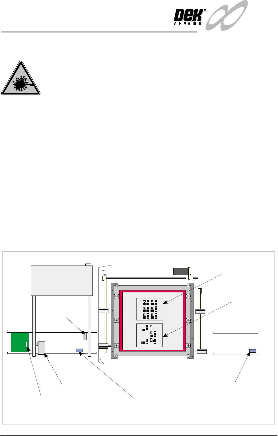
Figure 2-3 Board Load - Bar Code
Elements of the Dual Image Option
Front
Bar Code Reader
Bar Code Label
Input Conveyor Sensor
Output Conveyor Sensor
Product
‘Rear’ image
Product
‘Front’ image
Board
Present
Sensor