Infinity DI.pdf - 第58页
Chapter Issu e 3 Jan 01 Infinity Dual Imag e Manual 2.11 INFINITY OPERATOR TOOLING TOOLING The following board support tooling options are a vailable for use with the printer: • Magnetic Support Pillars • V acuum Box T o…
2.10 Infinity Dual Image Manual Chapter Issue 3 Jan 01
INFINITY
OPERATOR
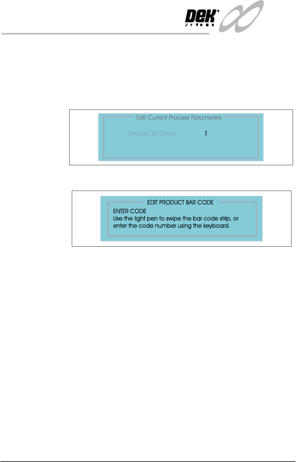
EDIT DATA
EDIT DATA The product bar code can be altered by swiping a label with a reader or by keying
in the code if it is known.
To edit the bar code follow the steps below:
1. Select Set Up (F6).
2. Select Edit Data (F3).
3. Select Bar Code from the ’Edit Process Page’.
4. Select incr. (F4). Enter the code using the options as shown.

Chapter Issue 3 Jan 01 Infinity Dual Image Manual 2.11
INFINITY
OPERATOR
TOOLING
TOOLING The following board support tooling options are available for use with the
printer:
• Magnetic Support Pillars
• Vacuum Box Tooling
• MultiFlex Tooling
• Dedicated Tooling Plate
• AutoFlex Tooling
• Fine Pitch AutoFlex
• ProFlow Stencil Support
Details of tooling options are given in the Board Support Tooling chapter of the
Infinity Technical Reference Manual.
When setting tooling for two images, the screen images may be for entirely
different products or for a single product printed both sides. In both cases any
tooling placed on the table must be positioned to give support for both images.
Hence, if tooling is placed for a first print run and the board is then flipped over
to be printed on the underside, the board is loaded to the same location for both
prints and tooling placed must accommodate both prints.
Features such as components, must not have tooling pins or support structures
placed for the first print run that would infringe upon the components on the
second print run.
Where vacuum tooling, for example a dedicated tooling plate is used, tooling
support must be given to underside components and first print features without
impairing the vacuum. If the second run had board features such as through
holes, vacuum would be impaired. The tooling must account for such features.
CAUTION
CAMERA DAMAGE. Do not leave any unused tooling on the rising table
in the area behind the rear rail. If any object is left on the rising table
outside the board printing area, it could collide with the camera carriage as
the rising table moves to print height.
2.12 Infinity Dual Image Manual Chapter Issue 3 Jan 01
INFINITY
OPERATOR
TOOLING
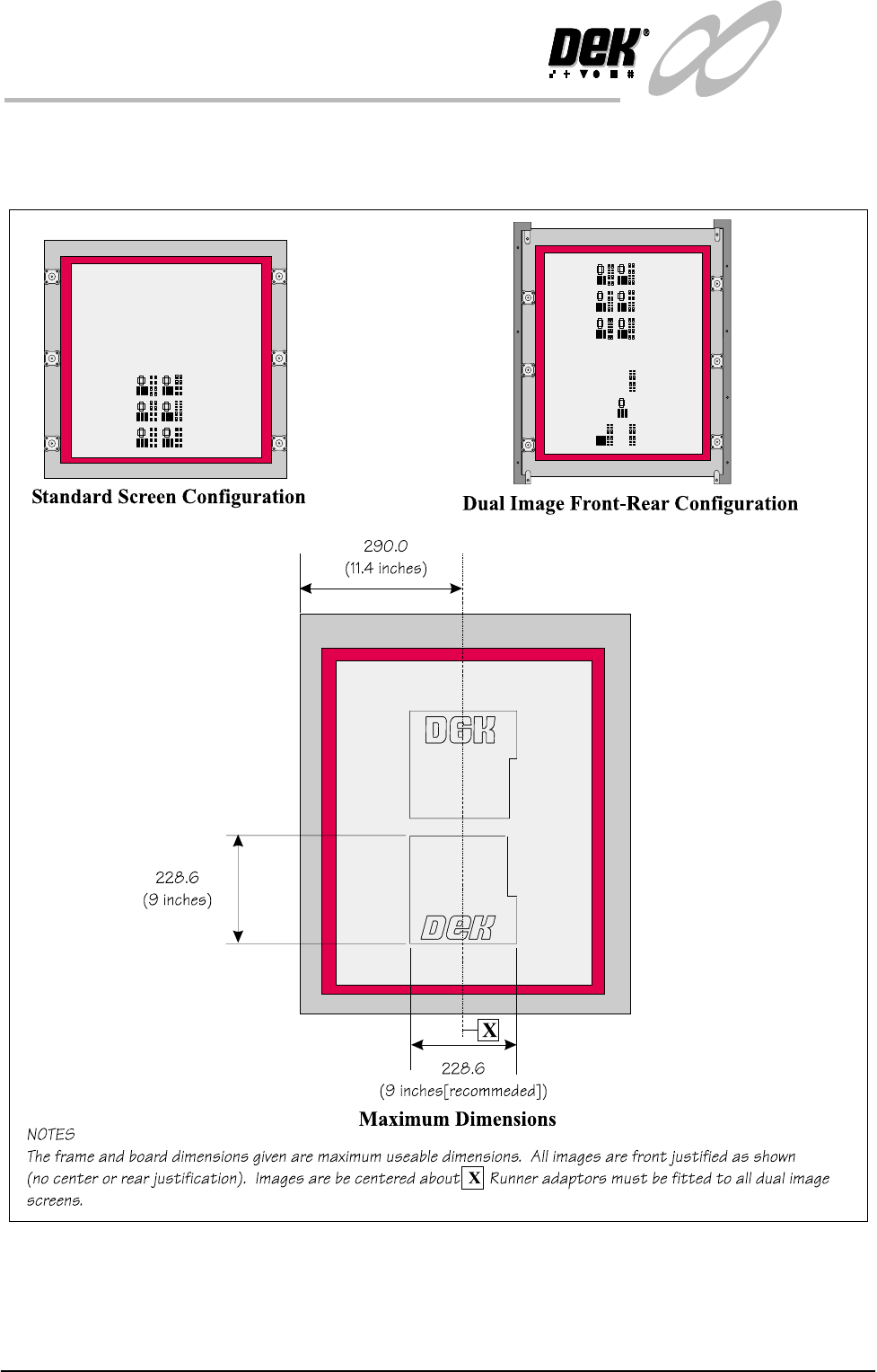
Maximum
Dimensions
The figure below describes the maximum useable dimensions for print in the
dual image mode. Tooling need only be placed within these boundaries