00198235-02_VD_710.1_R17-1_DE_EN.pdf - 第23页
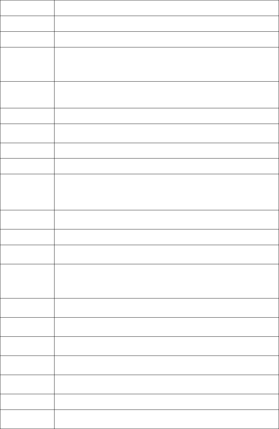
Station Software 71 0.1 (R17 - 1) / Versio n Description 06/2017 Edition 23 710.0 Patch 1 Error no. Error description D1 - 127726801 There wa s a message for all four hea ds that the vacuum wa s not sufficient. D1 - 1294…
Station Software 710.1 (R17-1) / Version Description 06/2017 Edition
22
D1-136325301 Error message 30016 Unhandled exception error after dp problem.
D1-136451420 With a LED camera an offset correction after ACT was not possible.
D1-136527301 The position of the y axis was out of the travel range.
D1-136558959
D1-136480611
D1-136558901
D1-136619501
The white light started to flash without any error.
D1-136584401 Although the error message segment down; do not move gantry was
displayed, the machine was going on with calibration and moved the gantry.
Reason: the error message was not reset.
D1-136649101 Big components were not displayed completely when they were tested.
D1-136667749 The nozzles were set up and a height reference run was started. Then the
software hung up in status
Checking nozzle configuration
.
D1-136703901 The Twin Head lost the nozzle when auto recovery was started.
D1-136707101 Although everything seemed to be fine, production of a board did not start.
D1-136708601 The software hung up when the pickup position was taught and had to be
rebooted.
Beim Teachen der Abholposition hing die GUI und die Maschine musste neu
gestartet werden.
D1-136720801 After the eSW download onto the WPC, the message The application
has to be closed
was displayed.
D1-136723403 The GUI closed when the error statistics were reset.
D1-136742701 The station software stopped during/after placement with error message
30016 Unhandled exception error
.
D1-136807601
D1-136828501
D1-137402984
D1-137403501
The endurance run stopped with too many repetitive errors.
D1-136860282 Head Verification: wrong z axis travel range values for Twin Head and VHF
placement heads.
D1-136872727 Head Verification: There was no summary when the verification was
completed.
D1-136872950 Head Verification: The test bench inspection function for Twin Head or
VHF placement heads displayed 4 buttons but only 2 were usable.
D1-136901201 Head Verification: The nozzle touched the component reject box when the
head was mounted in low position.
D1-136946001 The pickup position recognition worked only for small feeders on special
tracks.
D1-137345201 The machine did not stop after glass plate errors.
D1-137484901 After a SST47 camera error the head rejected all components behind the
camera.
Table 8-4: Corrected errors station software version 710.0 Patch 2
Station Software 710.1 (R17-1) / Version Description 06/2017 Edition
23
710.0 Patch 1
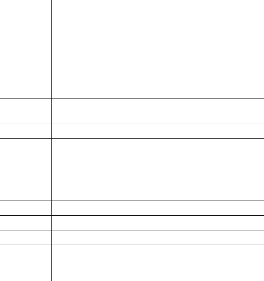
Error no. Error description
D1-127726801 There was a message for all four heads that the vacuum was not sufficient.
D1-129449544 eSW: the board was aborted when moving into PA2 but no errors were
displayed.
D1-135009301
D1-135456301
D1-135752301
The station stopped with a track error at the IPTE stick feeder but no error
message was displayed.
D1-135572407 Teaching did not work and a z-axis position error occurred.
D1-135681243 The overall endurance reference run could not be started.
D1-135712601 eSW: Opening and closing the cover lead to error message 30406 Power
output stage deactivated as a result of a faulty PWM
control signal
and the X-/Y-axes had to be referenced again.
D1-135745001 The reference run of the main axes failed.
D1-135752101 The WPC machine data could not be saved.
D1-135795401 After having corrected the pickup position, the station software did not respond
anymore.
D1-135841801 Calibrating the lifting table was not possible in Dual as single mode.
D1-135912801 There was a scale error when LED centering camera SST47 was used.
D1-135985601 A component on the glass plate was reported although there was none.
D17880-44541 All nozzles were thrown away after calibration.
D18082-6001 The machine stopped during production without any error.
D18093-11301 Changed placement offset after fiducials were whispered and the
measurement process was interrupted and then re-started.
D18263-1301 The cycle time was too long because the WPC and Twin Head were waiting
for the new board.
Table 8-5: Corrected errors station software version 710.0 Patch 1
Station Software 710.1 (R17-1) / Version Description 06/2017 Edition
24
9 Important Terms and Abbreviations
CA4 Machine type of the Chip Assembly (CA)-series with 4 gantries
and 2 PAs
C&P Collect & Place
CPP Collect & Place & Pick & Place
DC Dual Conveyor
DX1/DX2 Machine type with 1 or 2 gantries and 1 PA
EDIF Electronic Design Interchange Format
eWLP embedded Wafer Level Process
FOPLP Fan-Out Panel Level Packaging
FCCS Field Camera Calibration System
GUI Graphical User Interface
HFH High Force Head
HW Hardware
MGCU Modular Gantry Control Unit
MHCU Modular Head Control Unit
MTC Matrix Tray Changer
OIS Operator Information System
PA Processing area
PCB Printed circuit board
Placement mode:
2-in-1
When a machine runs in I-Placement mode, it is possible to
perform manual operations for one side / gantry. This placement
mode is also called "independent".
Placement mode:
Alternating
Placement mode in a dual gantry placement area, in which both
gantries place components on both boards in a dual conveyor.
First, both gantries place all assigned components on the board
in lane one and then on the board in lane two.
Placement mode:
Borrow
Performance
A line runs in I-Placement mode and to get a balanced
throughput between the left and right conveyor lanes, e.g. the
last machine runs in Alternating mode and places components in
this placement area on the board of the other lane.
Placement mode:
I-Placement
Placement mode in a dual gantry placement area in which each
gantry only places components on the board of the assigned
conveyor lane.
SC Single Conveyor
SC SIPLACE Setup Center (external setup control system)
SW Software
SWS SIPLACE Wafer System
SX1/SX2 Machine type with 1 or 2 gantries and 1 PA
TH Twin Head
TH HF Twin Head High Force