5OM-1434-003_w.pdf - 第136页
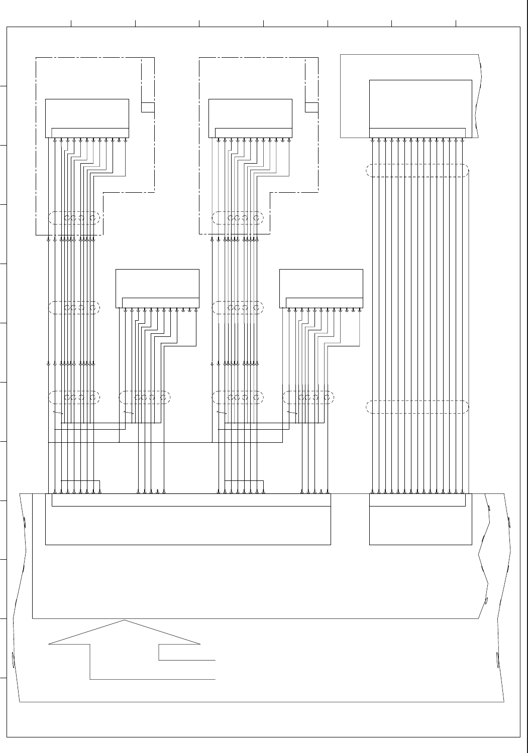
4-55 0710-001A(M858WR---0004) 䆛ࠀ䖳 TRG-B TRG-A GND TRG-D TRG-C 1 CN5 CN1 OUT-A1 +24V OUT-A4 +24V OUT-A3 CN6 OUT-A2 U94 U95 B44 B43 B42 B41 A43 A42 A41 8 7 6 5 56 55 54 53 A44 B36 B35 B34 B33 A35 A34 A33 16 15 14 13 64…
4-54
0710-001-(M858WR---0002)
䆛ࠀ䖳
2
3
15
CN2
1
5
6
9
10
8
7
14
13
12
11
4
4
2
7
10
1
5
8
11
3
6
9
12 VD-
HD+
Video-
TRGER
GND
HD-
GND
㧙
VD+
+12V
Video+
P. S
4
2
7
10
1
5
8
11
3
6
9
12 VD-
HD+
Video-
TRGER
GND
HD-
GND
㧙
VD+
+12V
Video+
P. S
P. S
Video+
+12V
VD+
㧙
GND
HD-
GND
TRGER
Video-
HD+
VD-12
9
6
3
11
8
5
1
10
7
2
4
VIDEO-Cam3
CTRL2-Cam3
HDrive-Cam3
VDrive-Cam2
VIDEO-Cam1
VDrive-Cam4
HDrive-Cam4
CTRL1-Cam3
VDrive-Cam3
GND
CTRL1-Cam2
CTRL2-Cam2
CTRL1-Cam1
CTRL1-Cam4
CTRL2-Cam4
+12V
VIDEO-Cam4
CTRL2-Cam1 24
22
21
20
19
18
16
15
2
13
12
11
10
9
7
4
3
1
25
26VDrive-Cam1
HDrive-Cam1
4
2
7
10
1
5
8
11
3
6
9
12 VD-
HD+
Video-
TRGER
GND
HD-
GND
㧙
VD+
+12V
Video+
P. S
CAMERA
PIO
X9201
20
1
19
8
10
6
18
2
7
9
13
12
17
3
16GND
PIO_2
Strobe_0
PIO_1
PIO_3
Trig_2
Trig_0
PIO_0
PIO_11(Strobe1)
GND
Trig_3
Trig_1
Strobe_2
PIO_15(Strobe3)
+5V_PIO
X9202
-X3601
-X6101
-X6101
X9502
U95
+12V 23
GND 6
VIDEO-Cam2 5
HDrive-Cam2 17
:2
:12
:9
:6
:3
:11
:8
:5
:1
:7
:4
-X13601
:2
:12
:9
:6
:3
:11
:8
:5
:1
:7
:4
GND 8
GND 14
-X23601
U92
:2
:12
:9
:6
:3
:11
:8
:5
:1
:7
:4
-X3601
-X13601 -X23601
ROBOT CABLE
ROBOT CABLE
HH-G300(1)
U
HH-G300(2)
U
(Frame Grabber 1)
:2
:12
:9
:6
:3
:11
:8
:5
:1
:7
:4
bus
D-B61(1)
M-B36(1)
M-B36(2)
D-B61(2)
1
2 3 4 5 6 7 8 9 10 11 12
A
B
C
D
E
F
G
H
Connector Case
Capture Trigger B1
Capture Trigger B2
Capture Trigger A1
Capture Trigger A2
GND
Electronic Flashing NG Signal A
Electronic Flashing NG Signal B
Reserved B
Electronic Flashing Signal
A
PEC Recognition Light ON Signal B
Electronic Flashing Signal
B
PEC Recognition Light ON Signal A
Reserved A
+5V
GND
Connector Case
Connector Case
Connector Case
Connector CaseConnector Case
Connector Case
Component Recognition Camera (1)
PEC
Recognition
Camera (1)
PEC
Recognition
Camera (2)
Component Recognition Camera (2)
Lighting Control Board
Recognition Board 1
Recognition BOX
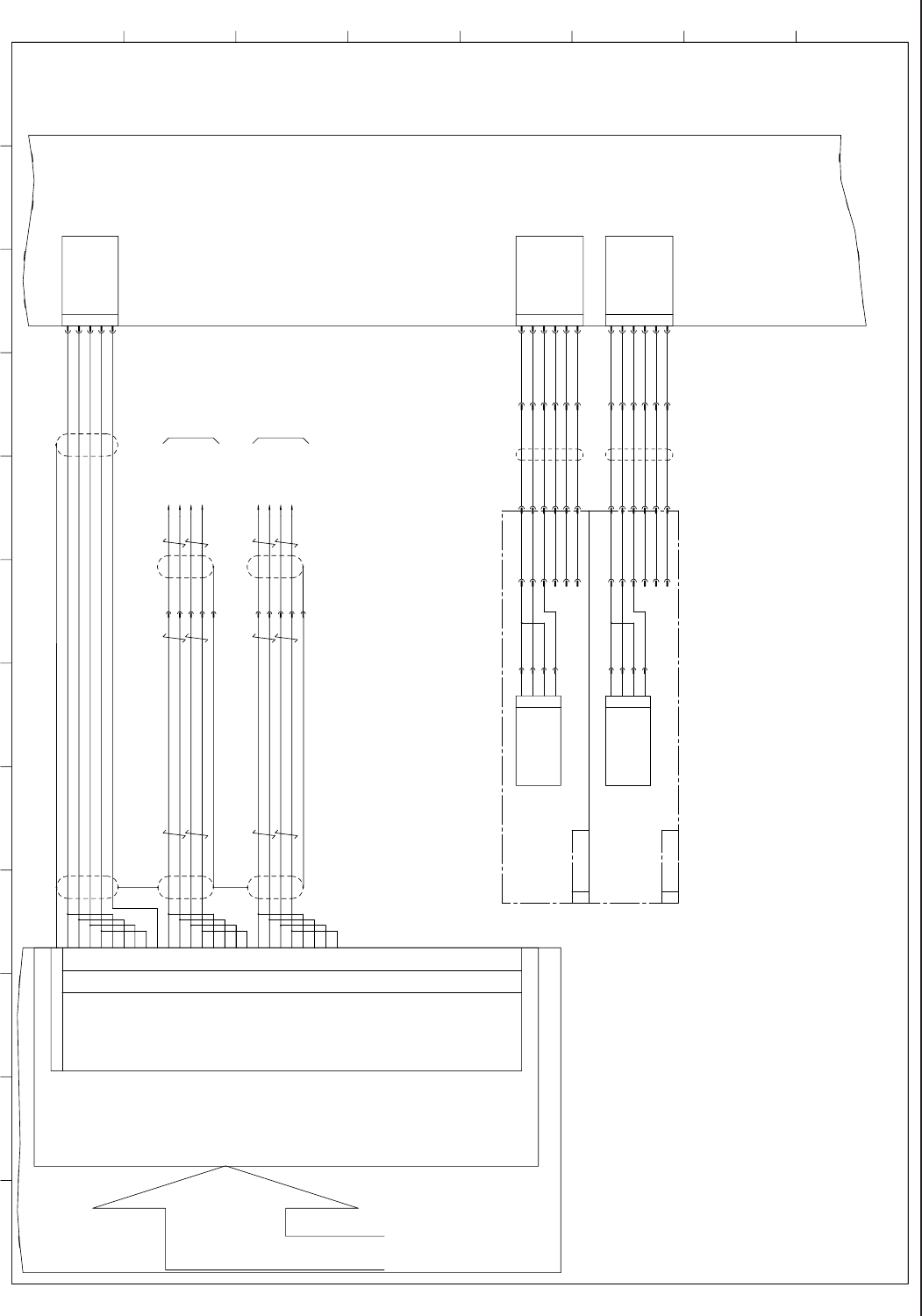
4-55
0710-001A(M858WR---0004)
䆛ࠀ䖳
TRG-B
TRG-A
GND
TRG-D
TRG-C
1
CN5
CN1
OUT-A1
+24V
OUT-A4
+24V
OUT-A3
CN6
OUT-A2
U94
U95
B44
B43
B42
B41
A43
A42
A41 8
7
6
5
56
55
54
53
A44
B36
B35
B34
B33
A35
A34
A33 16
15
14
13
64
63
62
61
A36
B28
B27
B26
B25
A27
A26
A25 24
23
22
21
72
71
70
69
A28
A20
77
78
79
80
29
30
31
32
41
91
90
93
92
42
43
44
45
A04
A05
A06
A07
B05
B04
B07
B06
A08
A17
A18
A19
B17
B18
B19
B20
CN7
[C-/01/5C]
[C-/01/7C]
2
3
4
5
1
2
3
4
5
6
OUT-A1
+24V
OUT-A4
+24V
OUT-A3
OUT-A2
1
2
3
4
5
6
ޛRobot Cableޜ
1
+24V
+24V
-E39(1)
-X19506
:1
:2
:3
:4
:5
:6
-X12507
:8
:9
:10
:11
:12
:13
2
3
4
-E61
-E39
-E39(2)
HH-G300(1)
U
HH-G300(2)
U
:1
:2
:3
:4
:5
:6
ޛRobot Cableޜ
ޛRobot Cableޜ
1
+24V
+24V
-X19506
:1
:2
:3
:4
:5
:6
-X12507
:8
:9
:10
:11
:12
:13
2
3
4
-E61
-E39
:1
:2
:3
:4
:5
:6
ޛRobot Cableޜ
X9507
X9506
bus
X9505
X9401
X19401
X29401
:1
:2
:5
:3
:3
:5
:2
:1
-X2405:6
-X2405:16
-X2405:7
-X2405:17
BA(1)
BA(2)
-X2405:17
-X2405:7
-X2405:16
-X2405:6
1
23456789101112
A
B
C
D
E
F
G
H
CH3 Actuation A Phase Input+
CH7 Actuation B Phase Input-
CH7 Actuation A Phase Input+
CH7 Actuation B Phase Input+
CH3 Actuation B Phase Input-
CH7 Actuation A Phase Input-
CH3 Actuation B Phase Input+
CH3 Actuation A Phase Input-
CH2 Actuation A Phase Input+
CH6 Actuation B Phase Input-
CH6 Actuation A Phase Input+
CH6 Actuation B Phase Input+
CH2 Actuation B Phase Input-
CH6 Actuation A Phase Input-
CH2 Actuation B Phase Input+
CH2 Actuation A Phase Input-
CH1 Actuation A Phase Input+
CH5 Actuation B Phase Input-
CH5 Actuation A Phase Input+
CH5 Actuation B Phase Input+
CH1 Actuation B Phase Input-
CH5 Actuation A Phase Input-
CH1 Actuation B Phase Input+
CH1 Actuation A Phase Input-
CH7 Single Shot Output
CH6 Single Shot Output
CH5 Single Shot Output
CH4 Single Shot Output
Connector Case
CH1 Single Shot Output
CH0 Single Shot Output
CH0 Actuation A Phase Input-
CH0 Actuation A Phase Input+
CH0 Actuation B Phase Input+
GND
CH2 Single Shot Output
CH3 Single Shot Output
CH4 Actuation A Phase Input-
CH0 Actuation B Phase Input-
CH4 Actuation B Phase Input+
CH4 Actuation A Phase Input+
CH4 Actuation B Phase Input-
Counter Board
Recognition
BOX
To Y Beam (1)-U24
㧛BPhase
BPhase
㧛APhase
A Phase
㧛BPhase
BPhase
㧛APhase
A Phase
To Y Beam (2)-U24
Lighting Control Board
PEC Recognition Lighting (Coaxial)
PEC Recognition Lighting (Ring)
PEC Recognition Lighting (Coaxial)
PEC Recognition Lighting (Ring)
PEC Recognition Lighting
PEC Recognition Lighting
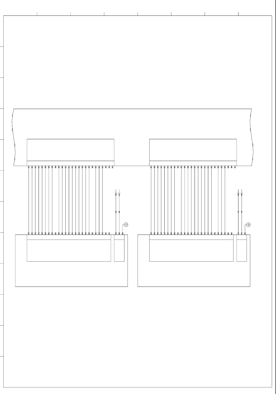
4-56
0710-001-(M858WR---0005)
䆛ࠀ䖳
FG
3
1
2
+24V
GND
10B
24B2L
6
4
5
2
3
1
7
9
8
16
17
15
14
12
13
10
11
18
19
21
20
23
22
24
25
+24V
BITA-8
SMI-A
SO-A-1
+24V
SO-A-0
COM
NC
NC
NC
BITA-1
NC
BITA-5
BITA-3
BITA-4
BITA-2
BITA-6
BITA-7
SV-A-4B
SV-A-4A
26
25
24
22
23
20
21
19
18
16
17
14
15
13
12
10
11
8
9
7
SV-A-2A
CN10
1
3
2
5
4
6
SV-A-3A
SV-A-2B
SV-A-3B
SV-A-1A
SV-A-1B
X9510
X6702
X6701
X6802
X9511
X6801
24B2L
10B
+24V
BITB-8
SMI-B
SO-B-1
+24V
SO-B-0
COM
NC
NC
NC
BITB-1
NC
BITB-5
BITB-3
BITB-4
BITB-2
BITB-6
BITB-7
SV-B-4B
SV-B-4A
26
25
24
22
23
20
21
19
18
16
17
14
15
13
12
10
11
8
9
7
SV-B-2A
CN11
1
3
2
5
4
6
SV-B-3A
SV-B-2B
SV-B-3B
SV-B-1A
SV-B-1B
FG
3
1
2
+24V
GND
6
4
5
2
3
1
7
9
8
16
17
15
14
12
13
10
11
18
19
21
20
23
22
24
25
BA -A67
BA -A68
U95
[BL/01/12C]
[BL/01/12C]
1
23456789101112
A
B
C
D
E
F
G
H
Back Lighting Open
Back Lighting Closed
Front Lighting 2
Open
Front Lighting 1
Open
Front Lighting 2 Closed
Front Lighting 1 Closed
Front Lighting 3 Closed
Front Lighting 3
Open
Light Control Output BIT7
Light Control Output BIT6
Light Control Output BIT2
Light Control Output BIT4
Light Control Output BIT3
Light Control Output BIT5
NC
Light Control Output BIT1
NC
COM(GND)
Flashing Trigger Signal 1
+24V
Flashing NG Signal Output
Light Control Output BIT8
Back Lighting Open
Back Lighting Closed
Front Lighting 2
Open
Front Lighting 1
Open
Front Lighting 2 Closed
Front Lighting 1 Closed
Front Lighting 3 Closed
Front Lighting 3
Open
Light Control Output BIT7
Light Control Output BIT6
Light Control Output BIT2
Light Control Output BIT4
Light Control Output BIT3
Light Control Output BIT5
Light Control Output BIT1
Flashing Trigger Signal 1
Flashing NG Signal Output
Light Control Output BIT8
+24V
NC
NC
NC
NC
COM(GND)
+24V
+24V
NC
NC
Component Recognition Lighting Sourse (1)
Component Recognition Lighting Sourse (2)
Lighting Control Board