46230812.pdf - 第15页
Page 13 TECHNICAL PUBLICATIONS DH Positioning System Assembly , P/T T46230812 Rev . D This Document Supports Assembly 46230812 Notes: 1 Torque to 90 IN-LBS. 2 Apply UIC # BLKM07389(Loctite 222), bottom plunger,then loose…
Page 12
TECHNICAL PUBLICATIONS
T46230812 Rev. D DH Positioning System Assembly, P/T
This Document Supports Assembly 46230812
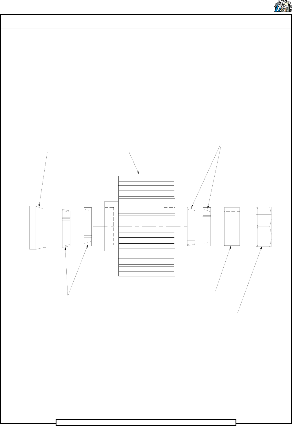
View - M
(Typical 2 Places)
Spacer
Locking Element
Locking Element
Hex Jam Nut
Spacer
Pulley Gearbelt

Page 13
TECHNICAL PUBLICATIONS
DH Positioning System Assembly, P/T T46230812 Rev. D
This Document Supports Assembly 46230812
Notes:
1
Torque to 90 IN-LBS.
2
Apply UIC # BLKM07389(Loctite 222), bottom plunger,then loosen 1/4 turn.
3
Apply UIC # BLKM07389(Loctite 222).
4
Torque screws to 70 IN-LBS.
5
Remove stop block and dowel pins when widths exceed 10.25 IN.
6
Used only with board widths up to 10.25 IN. Any board widths larger,remove quides and use
Det.62 as a board quide. Remove Det. 140 and replace with screws located on bad board hopper
bracket. When not using board guides, attach to bad board hopper bracket.
7
Lubricate ball bushing and shafts with 10W oil after assembly. Refer to X-Y Rotary Positioning
Assembly ball screw lubrication procedure.
8
Lable fittings and tubing with corresponding line numbers.
9
Torque screws to 30 IN-Lbs.
10
Remove existing set screws and replace with hardware indicted.
11
Apply UIC # BLKM07402 (LOCTITE 242).
12
Fasten with Loctite 495.
13
Apply UIC # BLKM07402(Loctite 242) to threads of ball screw units and torque nut to 15 FT-LBS.
14
Secure using the tapped hole that lies completely on pad.
15
Set-up dimension from the face of the bearing bracket to the face of the pulley hub.
16
Locate the pulley on the shaft with the set screw, then tighten the two # 8 socket head cap
screws to secure the pulley to the shaft.
17
Orient the extended hub of bearing to the right,when viewing the shaft from front of machine.
18
Do not wrap cable around encoder body.
19
Electrostatic discharge precautions must be used during assembly.
20
Completely wipe off rust preventative and apply Bluegrease(BLKM07680) thoroughly to ball screw
units .
21
Apply Magnalube (40833809) to top of plunger.
22
Dowel pins to protrude from encoder plate 0.12 inches toward motor mounting casting.
23
Keep ESD covers on connectors until cable connectors are attached.
24
Torque screws to 30 IN-Lbs.

Page 14
TECHNICAL PUBLICATIONS
T46230812 Rev. D DH Positioning System Assembly, P/T
This Document Supports Assembly 46230812
DET
NO.
ITEM NO. DESCRIPTION QTY U/M
1 48227901 BALL SCREW UNIT 2 EA
2 48253602 BELLOW,DUST 2 EA
3 BLKE01630 TIE,WRAP 1 EA
4 BLKM06540 NO-MAR SET SCR # 10-32 X 15/64 2 EA
5 80000516 SHCS 10-32 X 5/8 12 EA
6 48226701 MACHINING,DH X MOTOR 1 EA
7 80010512 DOWEL 1/2 DIA X 5 1 EA
8 80005005 SSSFP 1/4-20 X 1/2 1 EA
9 46991003 RETAINER,BELLOW 1 EA
10 80004805 SSSFP 8-32 X 3/8 4 EA
11 14338000 SHAFT, Y AXIS 2 EA
12 80000521 SHCS 10-32 X 1 1/2 14 EA
13 17702003 BASE 1 EA
14 12837000 GEARBELT 2 EA
15 47082601 SWITCH 4 EA
16 45121802 COUPLING,FLEX 2 EA
17 80019002 ITLW #4 14 EA
18 14346000 SWITCH,HOUSING 1 EA
19 80000304 SHCS 6-32 X 5/8 2 EA
20 80018803 FW #6 2 EA
21 80018703 SLW #6 4 EA
22 80010106 DOWEL 1/4 DIA X 1 1/4 2 EA
23 48257401 BRACKET 1 EA
24 80008408 PHMS 4-40 X 5/8 12 EA
25 14331000 COVER,HOUSING 1 EA
26 80000103 SHCS 4-40 X 3/8 8 EA
27 80010401 SDP 7/16 X 1 2 EA
28 BLKE01298 GROMMET 1 EA
29 14328001 PIN, ACTUATOR 4 EA
30 BLKM06319 RETAINING,RING 4 EA