46230812.pdf - 第45页
Page 43 TECHNICAL PUBLICATIONS DH Positioning System Assembly , P/T T46230812 Rev . D This Document Supports Assembly 46230812 When assembling the front board support and the front board guide, determine the edge clearan…
Page 42
TECHNICAL PUBLICATIONS
T46230812 Rev. D DH Positioning System Assembly, P/T
This Document Supports Assembly 46230812
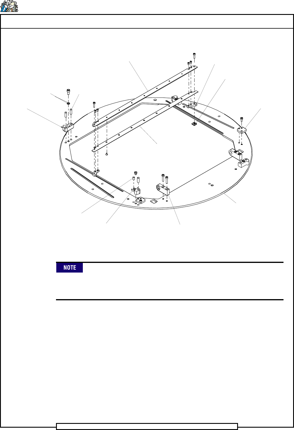
12. Remove the seven 6 - 32 x 3/16 button head screws that connect the
rear board guide to the rear board support.
13. If necessary, remove the two 10 - 32 x 3/8 cap screws that secure the
blocks to the rotary table and remove the blocks.
14. If necessary, remove the three 1/4 - 20 x 1/2 and one 1/4 - 20 x 1/4 cap
screws and dowel pins securing the four stops to the rotary table and
remove the stops.
15. Inspect all parts for wear or damage and replace as necessary.
16. Press seven 3/4 inch long and one 3/8 inch long dowel pins into the
rotary table. The 3/8 dowel pin must be installed in the front left stop
position shown.
17. Install the three stops to the rotary table using the 1/4 - 20 x 1/2 cap
screws and shaft spacers. Install the fourth stop to the rotary table
using the 1/4 - 20 x 1/4 low head cap screw in the front left stop
position shown.
18. Press the two blocks into the rotary table in the position shown. Using
a straight edge, square the blocks and secure to the rotary table using
the two 10 - 32 x 3/8 cap screws.
19. Assemble the rear board support and the rear board guide using the
seven 6 - 32 x 3/16 button head screws .
When assembling the rear board support and the rear board guide,
determine the edge clearance required for your specific system
configuration. Move the board support fully forward for a 5mm edge
clearance or fully rearward for a 3mm edge clearance.
20. Assemble the rear board support/guide assembly to the two rear
support blocks using the four 6 - 32 x 1/4 cap screws.
21. Install the rear board support/guide assembly to the rotary table using
the two 8 - 32 x 5/8 cap screws and two tee nuts.
Position the rear board support/guide assembly out of the way for the
remainder of this assembly procedure. It will be located as required
when the preproduction set up procedures are performed.
22. Assemble the front board support and the front board guide using the
seven 6 - 32 x 3/16 button head screws .
Page 43
TECHNICAL PUBLICATIONS
DH Positioning System Assembly, P/T T46230812 Rev. D
This Document Supports Assembly 46230812
When assembling the front board support and the front board guide,
determine the edge clearance required for your specific system
configuration. Move the board support fully forward for a 5mm edge
clearance or fully rearward for a 3mm edge clearance.
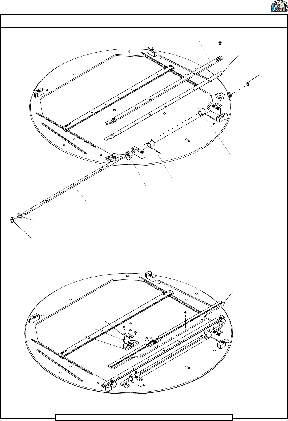
23. Install the front board support/guide to the rotary table assembly in the
position shown using the two 10 - 32 x 1/4 button head screws.
24. Assemble the tooling plate to the shaft in the position shown using the
five 6 - 32 x 3/8 cap screws.
25. Slide the two torsion springs onto the shaft noting the orientation of the
springs. Rotate the spring to apply tension and ensure that the springs
engage the cutout on the tooling plate.
26. Assemble the bearings into the bearing blocks and slide them onto the
shaft in the position shown.
27. Assemble retaining ring to the right end of the shaft.
3/4 Dowel Pin
Stop
3/8 Dowel Pin
Stop
Shaft Spacer
Rear Board
Guide
Rear Board
Support
Tee Nut
Rear Support
Block
Rotary Table
Block
Bearing Block
Page 44
TECHNICAL PUBLICATIONS
T46230812 Rev. D DH Positioning System Assembly, P/T
This Document Supports Assembly 46230812
Tooling Plate
Tooling
Pin Arm
Tooling Pin
Tooling Pin
Housing
Collar Clamp
Shaft
Radial
Bearing
Torsion
Spring
Retaining
Ring
Front Board
Support
Shaft Spacer
Board Guide
Torsion
Spring