46230812.pdf - 第23页
Page 21 TECHNICAL PUBLICATIONS DH Positioning System Assembly , P/T T46230812 Rev . D This Document Supports Assembly 46230812 Adjustment Procedures X-Y Axes Ball Bushing Preload Adjustments Purpose: The X and Y axis eac…
Page 20
TECHNICAL PUBLICATIONS
T46230812 Rev. D DH Positioning System Assembly, P/T
This Document Supports Assembly 46230812
Functional Description
The dual X-Y positioning system contains the X and Y positioning tables
which are actuated by the servo drive motors. When the motors receive a
signal they move the positioning system to predetermined coordinates
contained in the pattern program. Rotary encoders monitor the positioning
system location to ensure the positional accuracy. The X and Y tables mount
on the base and position the dual rotary tables.
Maintenance Concept
The following table defines the recommended Maintenance Concept for this
assembly. For a more detailed explanation of the Maintenance Concept and
its structure refer to the Prerequisite Information/Introduction module and the
periodic preventive maintenance as presented later in this document.
Maintenance Procedure
Recommended
Frequency
Minimum Skill
Requirement
Spares Kit
Required
Tool Kit
Required
Check rotary table squareness Weekly
Maintenance
Technician
No Yes
Check rotary table air motor drive
whee
l
Weekly
Maintenance
Technicia
n
No No
Lubricate the rotary table lock
assembl
y
Weekly
Maintenance
Technicia
n
No No
Flush and lubricate the X-Y ball
bushin
gs
Monthly
Maintenance
Technicia
n
No No
Clean and lubricate linear shafts Monthly
Maintenance
Technician
No No
Lubricate X-Y ball screws Monthly
Maintenance
Technician
No No
Disassemble, clean and lubricate
rotary table lock assy
Semiannually
Maintenance
Technician
No Yes
Prerequisite Information
• See the Prerequisite Information/Introduction document for Adhesive
and Lubricant icon information and definitions.
Page 21
TECHNICAL PUBLICATIONS
DH Positioning System Assembly, P/T T46230812 Rev. D
This Document Supports Assembly 46230812
Adjustment Procedures
X-Y Axes Ball Bushing Preload Adjustments
Purpose:
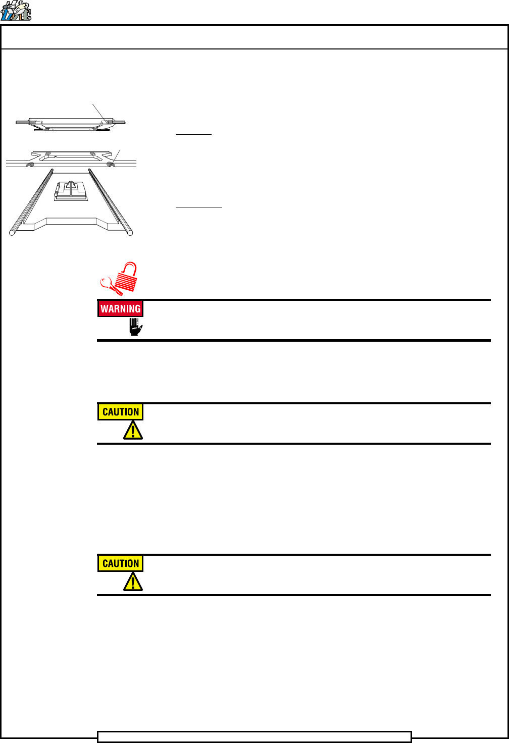
The X and Y axis each have four ball bushings. The ball bushings are
located one in each corner of the table. The locations of these ball bushings
are shown below.
Comments:
Initially these adjustments are done at the factory. If the ball bushings must
be replaced, the bearing preload adjustment must be performed.
1. Power down the machine. Execute your site's Lockout/Tagout
procedure.
The machine must be powered down and your site's Lockout/Tagout
procedure executed during this procedure to ensure personal safety.
2. Before installing the threaded spring plunger, apply a light coat of
Loctite 222 to the threads of the spring plunger.
Do not allow the sealant to enter the spring plunger tip area. No curing
time is required when using this adhesive.
3. Thread the spring plunger screw slowly into the table in a clockwise
direction so the screw begins to engage the threads. Stop when
resistance is felt against the spring plunger screw.
4. While rotating the ball bushing so the screw aligns with the bushing
slot, turn the spring plunger screw in until it bottoms.
Do not force the spring plunger screw past the point at which it bottoms
or damage to the ball bushing and spring plunger occurs.
5. Back the spring plunger screw out one quarter turn.
6. Repeat steps 1 through 4 for the remaining seven ball bushings.
End of procedure.
Ball Bushing Locations
BALL
X-
Y-
BASE
BALL
Page 22
TECHNICAL PUBLICATIONS
T46230812 Rev. D DH Positioning System Assembly, P/T
This Document Supports Assembly 46230812
X and Y Axes Ball Screw Unit Adjustment
Purpose:
Alignment of the ball screw unit axes to the support bearings is critical to the
proper function of the positioning system. Improper alignment of the ball
screw nut to the corresponding axis frame may result in misalignment of the
ball screw end in relationship to the support bearings for that axis. The
following procedure is intended to minimize the misalignment and system
drag load and thereby maximize bearing life.
Comments:
Initially these adjustments are done at the factory and should not be required
in the field. If the ball screw unit must be replaced in the field, the alignment
procedure must be performed.
Procedure:
1. Power down the machine. Execute your site's Lockout/Tagout
procedure.
The machine must be powered down and your site's Lockout/Tagout
procedure executed during this procedure to ensure personal safety.
2. Thoroughly clean the frame counterbores and if necessary, clean the
threads of the ball screw unit with a tap.
3. Loosen the mounting bolts on the bearing support blocks.
4. Install the dust bellows and protective covers over each ball screw unit.
5. Slide a ball screw unit through the mating bore in the support frame
and support the ends of the ball screw unit in the respective bearings.
6. Start the threads of the nut on the ball screw unit into the frame. Screw
the threads in until just before the aligning journal on the ball screw
unit is engaged. The ball screw unit should be loose.