46230812.pdf - 第32页
Page 30 TECHNICAL PUBLICATIONS T46230812 Rev . D DH Positioning System Assembly , P/T This Document Supports Assembly 46230812 Gear Belt Replacement Procedure: 1. Power down the machine. Execute your site's Lockout/…
Page 29
TECHNICAL PUBLICATIONS
DH Positioning System Assembly, P/T T46230812 Rev. D
This Document Supports Assembly 46230812
X and Y Axes Gear Belt Tension Adjustment
Procedure
Purpose:
X - Y Axes gear belts transfer motion from the motor assembly to the ball
screw unit which in turn moves the X or Y axis table positioning the printed
circuit board for component insertion. Due to the high degree of accuracy
required for component insertion and the speed between insertions, gear belts
must be kept at optimum tension. If the gear belt tension is too loose, table
over travel and therefore component misinsertion results. If the gear belt
tension is to tight, excessive gear belt and bearing wear results.
Comments:
This procedure is applicable to gear belt replacement and during gear belt
wear, resulting in gear belt stretch.
Because new belts stretch after approximately 150 hours of machine
operation, the gear belt tension must be reset after the initial 150 hours
of machine operation.
Gear Belt Tension Adjustment
Procedure:
1. Power down the machine. Execute your site's Lockout/Tagout
procedure.
The machine must be powered down and your site's Lockout/Tagout
procedure executed during this procedure to ensure personal safety.
2. Ensure the belt is correctly seated into both pulleys by rotating the
pulleys several rotations. This can be accomplished by moving the
appropriate axis by hand.
3. Loosen the three motor mounting bracket screws and allow the spring
mechanism in the encoder mounting plate to apply a force against the
side of the motor. The force is applied away from the lead screw
pulley and along the line between the centers of the pulleys.
4. With the force applied, again ensure the belt is correctly seated into
both pulleys by rotating the pulleys several rotations. This can be
accomplished by moving the appropriate axis by hand.
5. While the spring mechanism maintains the required force against the
side of the motor, tighten the three motor mounting bracket screws.
End of procedure.

Page 30
TECHNICAL PUBLICATIONS
T46230812 Rev. D DH Positioning System Assembly, P/T
This Document Supports Assembly 46230812
Gear Belt Replacement
Procedure:
1. Power down the machine. Execute your site's Lockout/Tagout
procedure.
The machine must be powered down and your site's Lockout/Tagout
procedure executed during this procedure to ensure personal safety.
2. Loosen the screws at the edge of the encoder mounting plate. This
action unloads the springs that apply pressure to the dowel pins.
3. Remove the three mounting screws that secure the motor mounting
bracket to the motor mount and carefully remove the motor and motor
mounting bracket assembly.
4. Loosen the two encoder coupling screws on the ball screw end of the
coupling, but do not remove.
5. Remove the screws on the encoder cover assembly and remove the
cover assembly.
6. Replace the gear belt.
7. Replace the encoder cover assembly, ensuring that the attached
coupling is mated to the ball screw shaft, then tighten the screws in the
encoder cover assembly.
8. Tighten the two screws in the ball screw end of the encoder coupling.
9. Install the motor and motor mounting plate assembly using the three
screws. Leave the screws loose enough to allow the dowel pins to
supply the correct tension.
10. Ensure that the gear belt is correctly seated in both gear belt pulleys by
rotating the pulleys several rotations. This can be done by moving the
appropriate axis by hand.
11. Tighten the screws at the edge of the encoder mounting plate so they
compress the springs which then apply a load to the dowel pins.
Ensure the motor is pushed away from the ball screw when the dowel
pins apply a load to the motor mounting bracket.
12. With the tension applied, again ensure that the gear belt is correctly
seated in both gear belt pulleys by rotating the pulleys several rotations.
13. Tighten the three screws on the motor mounting bracket.
End of procedure.
Page 31
TECHNICAL PUBLICATIONS
DH Positioning System Assembly, P/T T46230812 Rev. D
This Document Supports Assembly 46230812
X-Y Axes Encoder Adjustments
Purpose:
This procedure ensures that the positioning of the X-Y axis encoder settings
correspond with the position of head 1.
If any of the rotary encoders are misaligned, the head 1 position does not
correspond to the pattern program values.
Prerequisite Adjustment:
Rotary Disk Alignment
Special Tools:
Set Up Template (46367805)
Set up tool
(43806307 for jumper wire and large head tooling)
(43806311 for standard, 5mm and 5.5mm tooling)
(43806312 for 5mm s/l tooling)
Span Adjustment head (47088701)
Head Drive Shaft (47084401)
Adjustment Procedure:
1. Push the STOP button.
2. Palm the machine down as detailed in the Operation Manual, then set
the limit switch actuators to the following set up dimensions.
X-axis: 3/4 inch from the end of the X-frame casting to the end of
the limit switch actuator.
Y-axis: 1/4 inch from the end of the sheet metal actuator mounting
surface to the edge of the limit switch actuator block.
3. Using the head drive shaft tool, manually position the head tooling on
both insertion heads to the tool safe position to prevent possible
damage to the insertion tooling during positioning system movements.
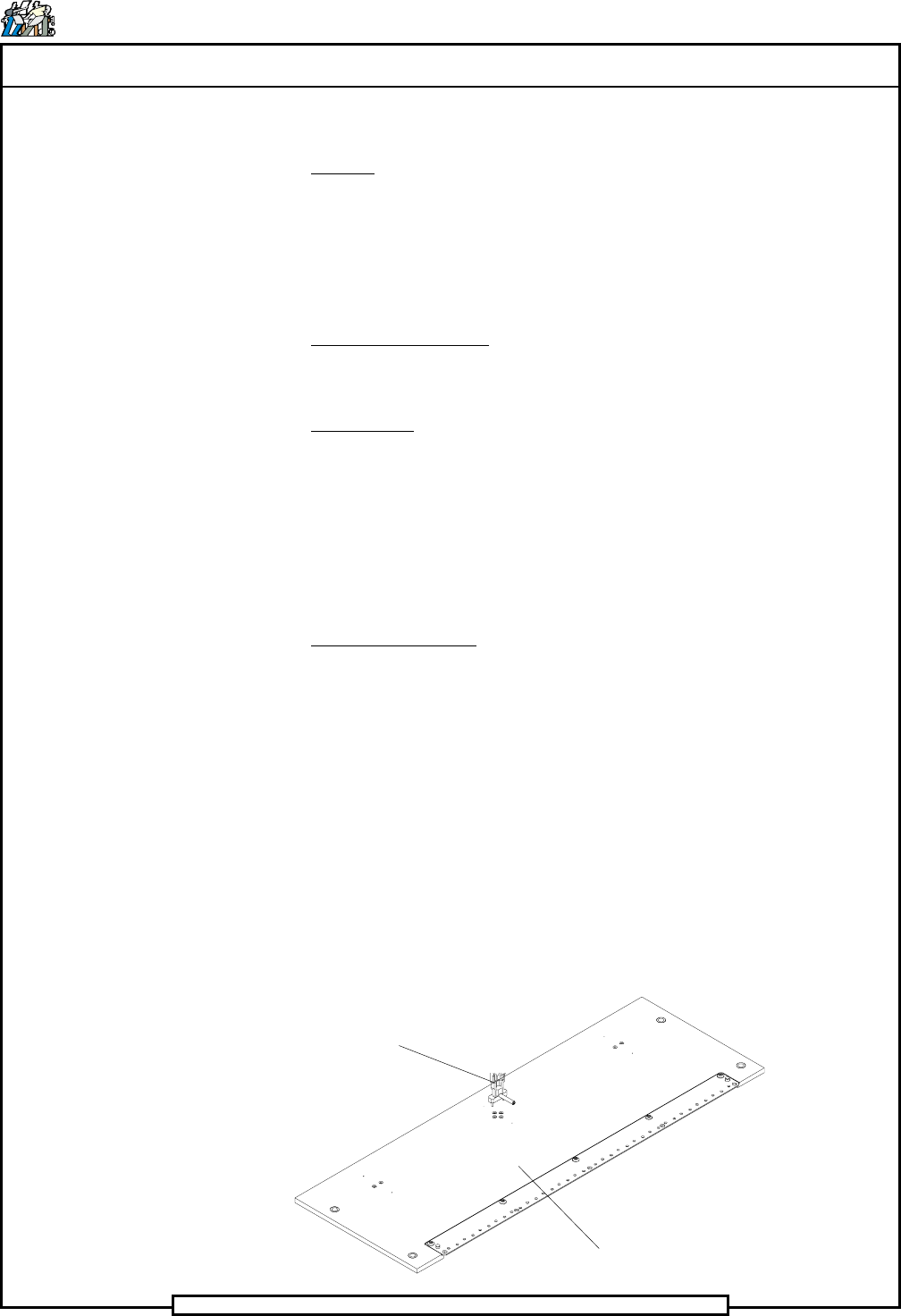
Set Up Template
Set Up Tool