46230812.pdf - 第50页
Page 48 TECHNICAL PUBLICATIONS T46230812 Rev . D DH Positioning System Assembly , P/T This Document Supports Assembly 46230812 14. Loosely install the left air cylinder assembly to the plate using the two 10 - 32 x 5/8 c…
Page 47
TECHNICAL PUBLICATIONS
DH Positioning System Assembly, P/T T46230812 Rev. D
This Document Supports Assembly 46230812
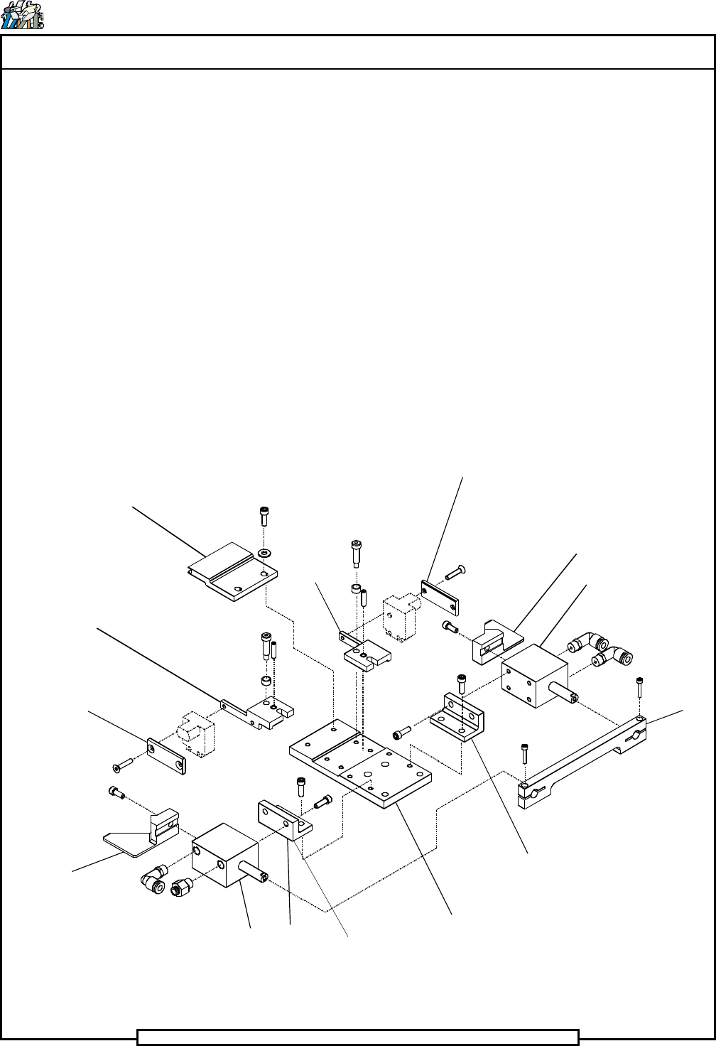
9. If necessary, remove the three male elbows and the straight fittings
from the air cylinders.
10. Inspect all parts for wear or damage and replace as necessary.
11. Install the male elbow and straight fitting to the left air cylinder, as
shown, and label them 107 and 106 respectively. Install the two male
elbow fittings to the right air cylinder, as shown, and label them 107
and 106 respectively.
12. Install the cylinder bracket to the left air cylinder using the two 10 - 24
x 1/2 cap screws. Perform the same for the right cylinder and cylinder
bracket.
13. Loosely install the left actuator to the left air cylinder piston. Rotate
the actuator counter clockwise until the flats on the piston shaft contact
the grove on the actuator then tighten the cap screws. Perform the
same for the right actuator and right air cylinder.
Front Board Guide
Switch Bracket
Strap
Actuator
Air Cylinder
Cylinder Bracket
Plate
Cylinder Bracket
Strap
Air Cylinder
Actuator
Switch
Bracket
Strap

Page 48
TECHNICAL PUBLICATIONS
T46230812 Rev. D DH Positioning System Assembly, P/T
This Document Supports Assembly 46230812
14. Loosely install the left air cylinder assembly to the plate using the two
10 - 32 x 5/8 cap screws. Perform the same for the right air cylinder
assembly. Loosely install the strap to the air cylinder pistons using the
two 6 - 32 x 3/4 cap screws as shown and move the strap up and down
to self align the air cylinders. Tighten the two 6 - 32 x 3/4 cap screws
securing the strap to the air cylinder pistons and the four 10 - 32 x 5/8
cap screws securing the air cylinder assemblies to the plate.
15. Manually move the air cylinders through the entire stroke to ensure
there is no binding. If any binding is present, loosen the screws
securing the cylinder bracket to the plate and the air cylinder to the
cylinder bracket and retighten.
16. Install the strap and sensor switch to the left switch bracket using the
two 8 - 32 x 7/8 cap screws. Perform the same for the strap and sensor
switch on the right switch bracket.
17. Install the two 10 - 32 x 3/4 set screws into the left and right switch
bracket assemblies.
18. Apply Tetra grease (UIC # 40833820) to the shoulders of the four
shoulder screws and Loctite #222 (UIC # BLKM07389) to the screw
threads of the four shoulder screws.
19. Slide the compression springs onto the shoulders of the four shoulder
screws. Install the left switch bracket assembly to the plate using the
shoulder screws and compression springs with the springs above the
switch bracket. Perform the same for the right switch bracket
assembly. The adjustment of the switch bracket assemblies will be
performed during the board handling final set up procedure.
20. Install the front board guide to the plate using the two 10 - 32 x 5/8 cap
screws and washers.
End of procedure
Page 49
TECHNICAL PUBLICATIONS
DH Positioning System Assembly, P/T T46230812 Rev. D
This Document Supports Assembly 46230812
Preventive Maintenance Schedule
Do not perform any preventive maintenance with power on unless
specifically instructed otherwise. Failure to observe this warning may
result in personal injury.
When performing machine maintenance, wear a wrist strap connected to
ground to prevent electrostatic discharge damage to printed circuit
boards.
Weekly (W): 1,500,000 Cycles
Check: Perform Maintenance:
1. Check the rotary table squareness. 1. Adjust as needed.
2. Check the rotary table air motor drive 2. Replace as needed.
wheel.
3. Lubricate the rotary table lock assembly with 10w
non-detergent oil.
4. Lubricate the actuator on the actuator assembly with
Kendall Super Blue grease.
Monthly (M): 6,000,000 Cycles
Check: Perform Maintenance:
1. Flush and lubricate the X/Y ball bushings with 10w
oil.
Semiannually (S): 36,000,000 Cycles
Check: Perform Maintenance:
1. Disassemble, clean and lubricate the rotary table
lock assembly per the assembly drawing. Replace
any worn parts.
2. Lubricate the X/Y ball lead screws with Kendall
Super Blue grease.
Dual Rotary Positioning Assembly Preventive Maintenance Details