6-9-p0027-0080-vx21_en.pdf - 第23页
∗ Options marked with are available for Class “H” coil. Applicable for all when the coil insulation class is Class “B”. Electrical Options (Special voltage, With light, Without DIN connector) VX2 Z 1A 1 0 A Enter stand…

48
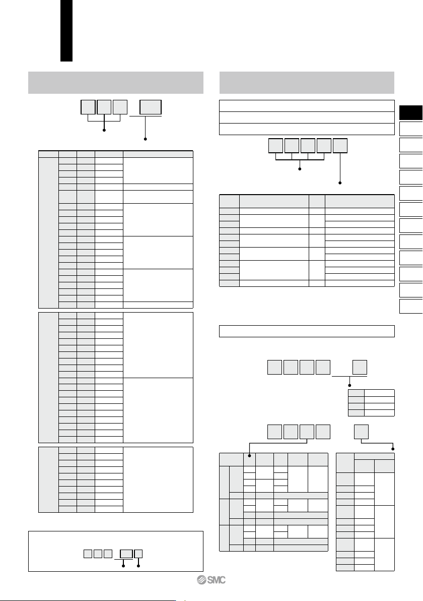
∗ Options marked with are available for Class “H” coil.
Applicable for all when the coil insulation class is Class “B”.
Electrical Options
(Special voltage, With light, Without DIN connector)
VX2
Z 1A1 0 A
Enter standard product
number.
Electrical option
Symbol
Low concentration ozone resistant and applicable
to deionized water
∗
1,
∗
3
(Seal material: FKM)
Port thread
Oil-free
Nil
A
B
C
D
E
F
G
H
K
L
Z
—
—
—
—
—
—
—
—
Rc, One-touch fitting
∗
2
G
∗
4
NPT
Rc, One-touch fitting
∗
2
G
∗
4
NPT
G
∗
4
NPT
Rc, One-touch fitting
∗
2
G
∗
4
NPT
Rc, One-touch fitting
∗
2
∗1 Applicable to air (VX20) and water (VX22).
∗2 When the body is resin, One-touch fittings are equipped.
∗3 When using deionized water or any other fluid that may corrode C37
(brass), select a stainless steel body.
∗4
For connection, prepare a fitting compliant with ISO 16030 and JIS B 8674.
Other Options
VX2
Z1 0 A A
Enter standard product
number.
Other option
Special voltage
Symbol
Specification
Electrical entryVoltage
1A
1B
1C
1U
1D
1E
1F
1G
1H
1V
1J
1K
1L
1M
1W
1N
1P
1Q
1R
1Y
1S
1T
48 VAC
220 VAC
240 VAC
24 VAC
12 VDC
12 VDC
48 VAC
220 VAC
240 VAC
24 VAC
12 VDC
48 VAC
220 VAC
240 VAC
24 VAC
12 VDC
48 VAC
220 VAC
240 VAC
24 VAC
12 VDC
12 VDC
Grommet
(With surge voltage suppressor)
DIN terminal
(With surge voltage suppressor)
Conduit terminal
(With surge voltage suppressor)
Conduit
(With surge voltage suppressor)
Flat terminal
Grommet
(With surge voltage suppressor)
Grommet
With light
2A
2B
2C
2D
2E
2F
2G
2H
2V
2J
2K
2L
2M
2N
2P
2Q
2R
2S
2W
2T
24 VDC
100 VAC
110 VAC
200 VAC
230 VAC
48 VAC
220 VAC
240 VAC
24 VAC
12 VDC
24 VDC
100 VAC
110 VAC
200 VAC
230 VAC
48 VAC
220 VAC
240 VAC
24 VAC
12 VDC
DIN terminal
(With surge voltage suppressor)
Conduit terminal
(With surge voltage suppressor)
Without DIN connector
3A
3B
3C
3D
3E
3F
3G
3H
3V
3J
Class H
∗
—
—
—
—
—
—
—
—
—
—
—
—
—
—
—
—
—
—
—
24 VDC
100 VAC
110 VAC
200 VAC
230 VAC
48 VAC
220 VAC
240 VAC
24 VAC
12 VDC
DIN terminal
(With surge voltage suppressor)
Electrical specification/Voltage/Electrical entry
Low concentration ozone resistant and applicable to deionized water
Oil-free
Port thread
Low concentration ozone resistant and applicable to deionized water/Oil-free/Port thread
Example) VX2 Z Z1A1 2 A
Electrical option Other option
∗ Enter symbols in the order below when ordering a combination of
electrical option, other option, etc.
XL1
XL2
XL3
XL4
600 mm
1000 mm
1500 mm
3000 mm
VX2 XL
Lead wire length
Made to Order
VX2 XH
1
2
3
N.C.
N.O.
N.C.
N.O.
N.C.
N.O.
Q
R
S
T
—
Q
R
—
—
Q
R
—
—
1/8
1/4
1/8
1/4
1/4
3/8
1/4
3/8
2
3
3
2 MPa
2 MPa
3 MPa
C37
Stainless steel
—
C37
Stainless steel
—
C37
Stainless steel
—
Orifice
dia.
Body
material
Port
size
Not available
Not available
Not available
Not available
Not available
Max. operating
pressure differential
Size
Symbol
Correspondence table
<Special lead wire length>
Produced upon receipt of order.
<High pressure>
90°
180°
270°
In side
(Standard)
90°
180°
270°
In side
(Standard)
90°
180°
270°
In side
(Standard)
Electrical
entry direction
Bracket
None
With
bracket
Mounting
holes on
the bottom
side of
the body
Specifications
Symbol
Nil
A
B
C
D
E
F
G
H
J
K
L
Option
∗ The aluminum and PBT bodies are not
available.
49
VX21/22/23 Series
Special Options
VX2
VXK
VXD
VXZ
VXS
VXB
VXE
VXP
VXR
VXH
VXF
VX3
VXA
VX2
D
IN OUT
IN OUT
IN OUT
90°
180°
270°
IN OUT
IN OUT
IN OUT
90°
180°
270°
90°
180°
270°
IN
OUT
90°
180°
270°
VX2
A
Enter standard product
number.
U
W
X
Size
1
2
3
Port size
1/8, 1/4
1/4, 3/8
1/4, 3/8
1/2
U
46
56
56
—
W
36
46
46
—
X
11
13
13
—
(mm)
With bracket/Special
electrical entry direction
Symbol
A
Nil
Symbol
B
C
Electrical entry direction
Standard
Electrical entry direction
XB
XC
XB
XNB
X332
Special electrical entry direction
Symbol
With bracket Mounting holes on the bottom side of the body Seal material: EPDM
Bracket Interchangeable with an Old Type
Size
1
2
3
Port size
1/8, 1/4
1/4, 3/8
1/4, 3/8
1/2
Orifice diameter (mmø)
2
3
5
4
7
5
8
10
10
Bracket interchangeable with an old type
(Interchangeable)
(Interchangeable)
(Interchangeable)
(Interchangeable)
(Interchangeable)
(Interchangeable)
(Not interchangeable)
∗
2
(Not interchangeable)
∗
2
— (Not available)
∗
2
∗1
Bracket is attached as standard with the resin body, so there are no XB settings.
∗2
When the orifice is ø8, ø10, and the body port size is 1/4 or 3/8, use a foot
type bracket. (The L-bracket of the old VX series is not compatible.) If the
body port size is 1/2, there are no XB settings. (Refer to the following.)
∗3
On the bottom side of the standard body, there is no female thread for mounting
a bracket. Please be careful because the bracket cannot be retrofit.
∗4 Bracket is packed in the same container as the main body.
Example)
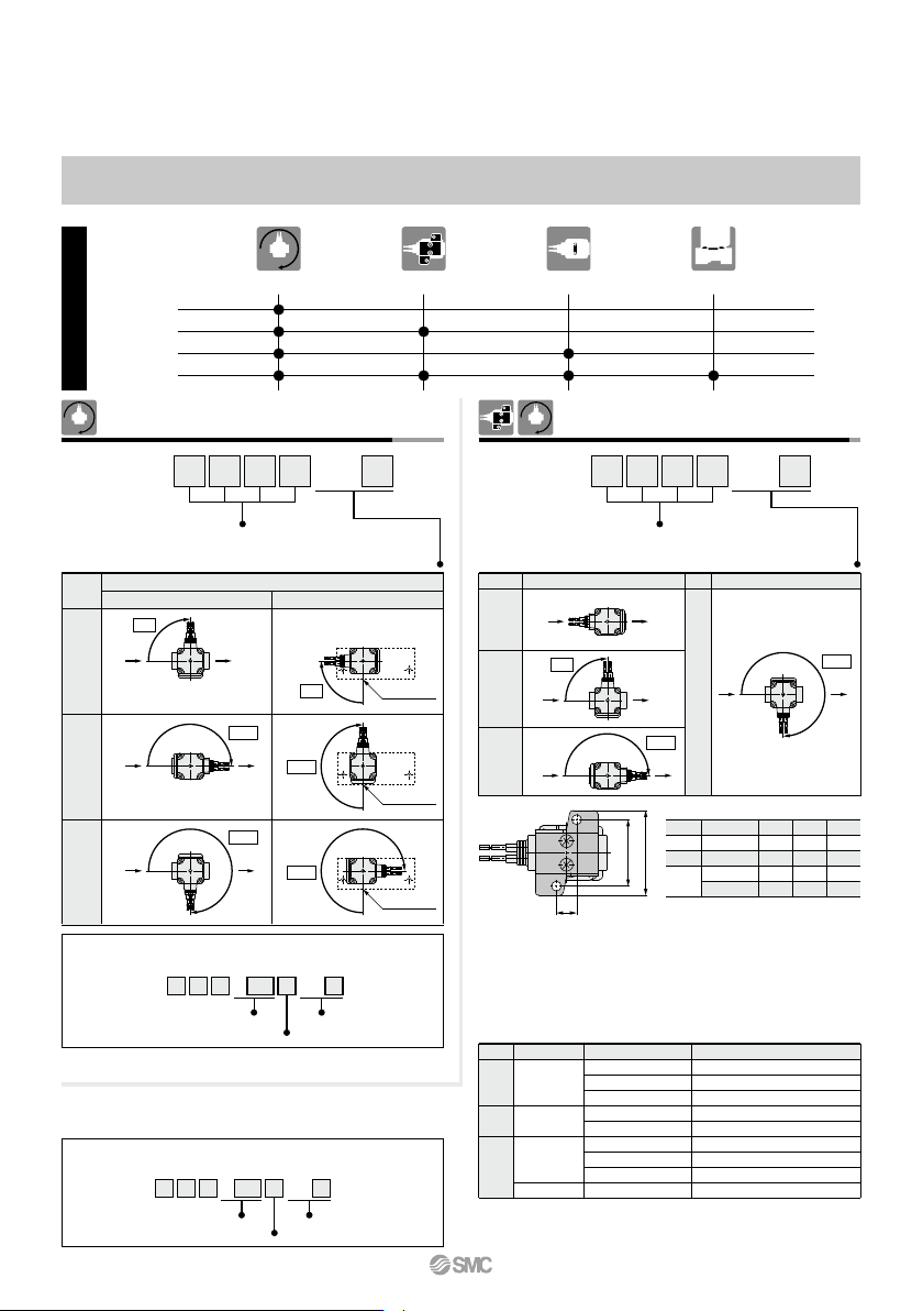
VX2 Z Z1A XB1 2 A
Electrical option
A
Other option
With bracket/Special
electrical entry direction
∗ Enter symbols in the order below when ordering a combination of
electrical option, other option and with bracket.
Installation Options
(Mounting Option/Special Electrical Entry Direction)
Combinations
VX2 XC
Enter standard product
number.
Special Electrical Entry Direction
Special electrical entry direction
Symbol
A
B
C
Electrical entry direction
Single unit Manifold
90°
180°
270°
90°
180°
270°
A
Individual port
Individual port
Individual port
Example) VX2 Z Z1A XC1 2 A
Electrical option
A
Other option
Special electrical
entry direction
∗ Enter symbols in the order below when ordering a combination of
electrical option, other option and special electrical entry direction.
The following shows combinations that can be selected using installation options.
With Bracket/
Special Electrical Entry Direction
50
VX21/22/23 Series