6-9-p0027-0080-vx21_en.pdf - 第51页
VX21 VX22 VX23 0.5 0.7 Proper Tightening Torque (N·m) Metal body ( Aluminum C37 Stainless steel ) Resin body Mounting screw Coil assembly O-ring A O-ring B Adapter Push rod assembly Spring O-ring C Mounting screw Coil as…
Mounting
Warning
Selection
AC coil: 5% or less of rated voltage
DC coil: 2% or less of rated voltage
Caution
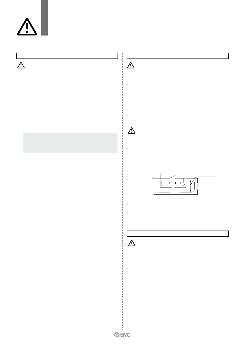
1. Leakage voltage
When the solenoid valve is operated using the controller, etc.,
the leakage voltage should be the product allowable leakage
voltage or less. Particularly when using a resistor in parallel
with a switching element and using a C-R element (surge
voltage suppressor) to protect the switching element, take note
that leakage current will flow through the resistor, C-R element,
etc., creating a possible danger that the valve may not turn off.
2. Selecting model
Material depends on fluid. Select optimal models for the fluid.
3. When the fluid is oil.
The kinematic viscosity must not exceed 50 mm
2
/s.
1. If air leakage increases or equipment does not
operate properly, stop operation.
After mounting is completed, confirm that it has been done
correctly by performing a suitable function test.
2. Do not apply external force to the coil section.
When tightening is performed, apply a wrench or other tool to
the outside of the piping connection parts.
3. Mount a valve with its coil position upward, not
downward.
When mounting a valve with its coil positioned downward,
foreign objects in the fluid will adhere to the iron core leading
to a malfunction. Especially for strict leakage control, such as
with vacuum applications and non-leak specifications, the coil
must be positioned upward.
4. Do not warm the coil assembly with a heat insulator
etc.
Use tape, heaters, etc., for freeze prevention on the piping and
body only. They can cause the coil to burn out.
5. Low temperature operation
1) The valve can be used in an ambient temperature of between
–20 to –10°C. However, take measures to prevent freezing or
solidification of impurities, etc.
2) When using valves for water application in cold climates, take
appropriate countermeasures to prevent the water from
freezing in tubing after cutting the water supply from the
pump, by draining the water etc. When warming by a heater
etc., be careful not to expose the coil portion to a heater.
Installation of a dryer, heat retaining of the body is recom-
mended to prevent a freezing condition in which the dew
point temperature is high and the ambient temperature is low,
and the high flow runs.
Warning
R
SOL.
OFF
Switching element
C
Power supply
Leakage voltage
Leakage current
Selection
Warning
<Water>
Be aware that rust stains, chloride separation, etc., from the piping may
cause malfunction, leakage, or, in worse case scenarios, damage due
to corrosion. Also, such damage may result in the spraying of fluids or
scattering of parts. Please be sure to have protective measures in place
in case such incidents should occur.
The use of a fluid that contains foreign objects can cause problems
such as malfunction and seal failure by promoting wear of the valve
seat and armature and by sticking to the sliding parts of the
armature etc. Install a suitable filter (strainer) immediately upstream
from the valve. As a general rule, use 100 mesh.
The supply water includes materials that create a hard sediment or
sludge such as calcium and magnesium. Since this scale and
sludge can cause the valve to malfunction, install water softening
equipment, and a filter (strainer) directly upstream from the valve to
remove these substances.
Tap water pressure:
The water pressure for tap water is normally 0.4 MPa or less. How-
ever, in places like a high-rise building, the pressure may be 1.0 MPa.
When selecting tap water, be careful of the maximum operating pres-
sure differential.
When using water or heated water, poor operation or leaks
may be caused by dezincification, erosion, corrosion, etc. We
offer a stainless steel body type with improved corrosion
resistance. Please use the one that fits your needs.
<Oil>
Generally, FKM is used as seal material, as it is resistant to
oil. The resistance of the seal material may deteriorate
depending on the type of oil, manufacturer or additives.
Check the resistance before using. The kinematic viscosity
must not exceed 50 mm
2
/s.
<Steam>
The use of a steam that contains foreign objects can cause
problems such as malfunction and seal failure by promoting wear of
the valve seat and armature, and by sticking to the sliding parts of
the armature etc. Install a suitable filter (strainer) immediately
upstream from the valve.
As a standard, the mesh count for the strainer is 100 mesh.
However, the size and shape of foreign objects that occur depends
on the operating environment. Check the fluid status and choose an
appropriate mesh count.
The supply water to a boiler includes materials that create a hard
sediment or sludge such as calcium and magnesium.
Sediment and sludge from steam can cause the valve to not operate
properly. Install a water softening device, which removes these
materials. Do not use operation steam which contains chemicals,
synthetic oils containing organic solvents, salts or corrosive gases,
etc., as these can cause damage or deterioration.
The seal material (special FKM) used for wetted parts of the product
can withstand steam in standard conditions.
However, the resistance of the sealing material can deteriorate
depending on the types of additives such as boiler compounds and
water conditioners within the boiler steam. Please only utilize the
product after determining the sealing material resistance within the
actual usage conditions.
3. Ambient environment
Use within the operable ambient temperature range. Check
the compatibility between the product’s composition materials
and the ambient atmosphere. Be certain that the fluid used
does not touch the external surface of the product.
4. Countermeasures against static electricity
Take measures to prevent static electricity since some fluids
can cause static electricity.
VX21/22/23 Series
Specific Product Precautions 2
Be sure to read this before handling the products.
Refer to back page 50 for Safety Instructions and pages 17 to 19 for 2 Port Solenoid
Valve for Fluid Control Precautions.
74
C
VX21
VX22
VX23
0.5
0.7
Proper Tightening Torque
(N·m)
Metal body (
Aluminum
C37
Stainless steel
)
Resin body
Mounting screw
Coil assembly
O-ring A
O-ring B
Adapter
Push rod assembly
Spring
O-ring C
Mounting screw
Coil assembly
Seal
Return spring
Armature assembly
Body
Bracket
4
3
2
1
No gaps
Mounting Disassembly/Assembly Procedures
Warning Caution
5.
Secure with brackets, except in the case of steel piping
and copper fittings.
6.
Avoid sources of vibration, or adjust the arm from the body
to the minimum length so that resonance will not occur.
7. Painting and coating
Warnings or specifications printed or labeled on the product
should not be erased, removed or covered up.
Caution
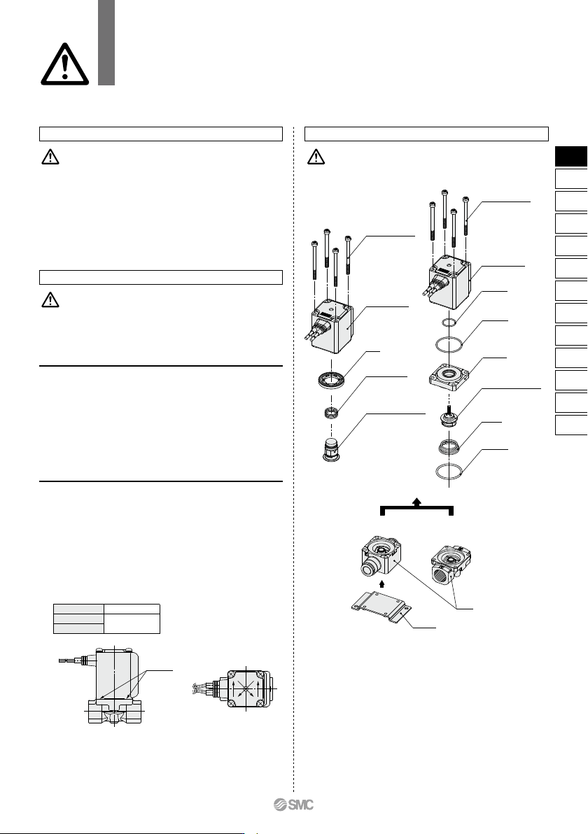
1. Before starting the disassembly work, be sure to
shut off the power supply and pressure supply, and
then release the residual pressure.
<N.C.>
1) Loosen the mounting screws.
The coil assembly, seal, return spring, armature assembly and
body can be removed.
<N.O.>
1) Loosen the mounting screws.
The coil assembly, push rod assembly, O-rings, adapter and
body can be removed.
Disassembly
<Common to N.C. and N.O.>
1) Mount the components on the body in the reverse order of
disassembly.
2) When changing the electrical entry direction, turn the coil
assembly in a desired direction to mount it.
3)
Push the coil assembly against the body and tighten the screws
two or more rounds diagonally (Fig. 2) in the status that there
are no gaps between the coil assembly and body (Fig. 1).
Tighten the screws in the order of “12341234”.
∗ After tightening the screws, make sure that there are no gaps between the
coil and body (Fig. 1).
∗ After the disassembly and assembly have been completed, make sure
that no leak occurs from the seal. Additionally, when restarting the valve,
make sure that the valve operates correctly after checking the safety.
Assembly
Fig.2Fig.1
<N.C.> <N.O.>
Disassembly/Assembly Procedures
VX21/22/23 Series
Specific Product Precautions 3
Be sure to read this before handling the products.
Refer to back page 50 for Safety Instructions and pages 17 to 19 for 2 Port Solenoid
Valve for Fluid Control Precautions.
75
VX2
VXK
VXD
VXZ
VXS
VXB
VXE
VXP
VXR
VXH
VXF
VX3
VXA
VX2
Disassembly/Assembly Procedures
Caution
Piping
Warning
Caution
1. During use, deterioration of the tube or damage to
the fittings could cause tubes to come loose from
their fittings and thrash about.
To prevent uncontrolled tube movement, install protective
covers or fasten tubes securely in place.
2. For piping the tube, fix the product securely using the
mounting holes so that the product is not in the air.
1. Preparation before piping
Before piping is connected, it should be thoroughly blown out
with air (flushing) or washed to remove chips, cutting oil and
other debris from inside the pipe. Avoid pulling, compressing, or
bending the valve body when piping.
2. Avoid connecting ground lines to piping, as this may
cause electric corrosion of the system.
3. Always tighten threads with the proper tightening
torque.
When using steel piping, tighten with the proper tightening
torque shown below.
Lower tightening torque will lead into fluid leakage.
4. Connection of piping to products
When connecting piping to a product, avoid mistakes regarding
the supply port etc.
5. Winding of sealant tape
When connecting pipes, fittings,
etc., be sure that chips from the
pipe threads and sealing material
do not enter the valve.
Furthermore, when sealant tape is
used, leave 1.5 to 2 thread ridges
exposed at the end of the threads.
6. In applications such as vacuum and non-leak speci-
fications, use caution specifically against the
contamination of foreign objects or airtightness of
the fittings.
Tightening Torque for Piping
Thread size
Rc1/8
Rc1/4
Rc3/8
Rc1/2
7 to 9
12 to 14
22 to 24
28 to 30
Proper tightening torque (N·m)
Individual SUP
for medium vacuum
Common SUP
for air
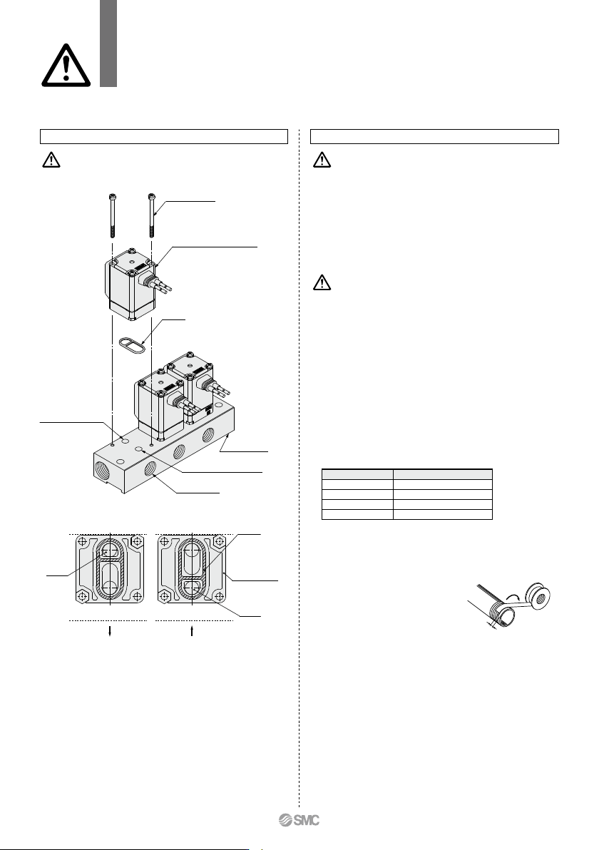
Manifold Exploded View
IN port (Common SUP)
OUT port (Individual SUP)
IN port
Gasket
IN port
Solenoid valve for manifold
Gasket
Mounting screw
OUT port (Common SUP)
IN port (Individual SUP)
Individual port sideIndividual port side
∗ Mounting orientation exists when mounting valves onto manifold base.
Mount it as shown above.
∗ Take great care when special electrical entry direction (XC) is used.
Individual port
Solenoid valve
interface for
manifold
Manifold base
VX21/22/23 Series
Specific Product Precautions 4
Be sure to read this before handling the products.
Refer to back page 50 for Safety Instructions and pages 17 to 19 for 2 Port Solenoid
Valve for Fluid Control Precautions.
Winding
direction
Sealant tape
Expose approx.
2 threads
76