6-9-p0027-0080-vx21_en.pdf - 第52页
Disassembly/Assembly Procedures Caution Piping Warning Caution 1. During use, deterioration of the tube or damage to the fittings could cause tubes to come loose from their fittings and thrash about. To prevent uncontrol…
VX21
VX22
VX23
0.5
0.7
Proper Tightening Torque
(N·m)
Metal body (
Aluminum
C37
Stainless steel
)
Resin body
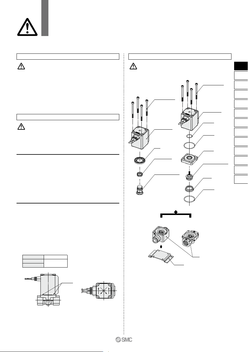
Mounting screw
Coil assembly
O-ring A
O-ring B
Adapter
Push rod assembly
Spring
O-ring C
Mounting screw
Coil assembly
Seal
Return spring
Armature assembly
Body
Bracket
4
3
2
1
No gaps
Mounting Disassembly/Assembly Procedures
Warning Caution
5.
Secure with brackets, except in the case of steel piping
and copper fittings.
6.
Avoid sources of vibration, or adjust the arm from the body
to the minimum length so that resonance will not occur.
7. Painting and coating
Warnings or specifications printed or labeled on the product
should not be erased, removed or covered up.
Caution
1. Before starting the disassembly work, be sure to
shut off the power supply and pressure supply, and
then release the residual pressure.
<N.C.>
1) Loosen the mounting screws.
The coil assembly, seal, return spring, armature assembly and
body can be removed.
<N.O.>
1) Loosen the mounting screws.
The coil assembly, push rod assembly, O-rings, adapter and
body can be removed.
Disassembly
<Common to N.C. and N.O.>
1) Mount the components on the body in the reverse order of
disassembly.
2) When changing the electrical entry direction, turn the coil
assembly in a desired direction to mount it.
3)
Push the coil assembly against the body and tighten the screws
two or more rounds diagonally (Fig. 2) in the status that there
are no gaps between the coil assembly and body (Fig. 1).
Tighten the screws in the order of “12341234”.
∗ After tightening the screws, make sure that there are no gaps between the
coil and body (Fig. 1).
∗ After the disassembly and assembly have been completed, make sure
that no leak occurs from the seal. Additionally, when restarting the valve,
make sure that the valve operates correctly after checking the safety.
Assembly
Fig.2Fig.1
<N.C.> <N.O.>
Disassembly/Assembly Procedures
VX21/22/23 Series
Specific Product Precautions 3
Be sure to read this before handling the products.
Refer to back page 50 for Safety Instructions and pages 17 to 19 for 2 Port Solenoid
Valve for Fluid Control Precautions.
75
VX2
VXK
VXD
VXZ
VXS
VXB
VXE
VXP
VXR
VXH
VXF
VX3
VXA
VX2
Disassembly/Assembly Procedures
Caution
Piping
Warning
Caution
1. During use, deterioration of the tube or damage to
the fittings could cause tubes to come loose from
their fittings and thrash about.
To prevent uncontrolled tube movement, install protective
covers or fasten tubes securely in place.
2. For piping the tube, fix the product securely using the
mounting holes so that the product is not in the air.
1. Preparation before piping
Before piping is connected, it should be thoroughly blown out
with air (flushing) or washed to remove chips, cutting oil and
other debris from inside the pipe. Avoid pulling, compressing, or
bending the valve body when piping.
2. Avoid connecting ground lines to piping, as this may
cause electric corrosion of the system.
3. Always tighten threads with the proper tightening
torque.
When using steel piping, tighten with the proper tightening
torque shown below.
Lower tightening torque will lead into fluid leakage.
4. Connection of piping to products
When connecting piping to a product, avoid mistakes regarding
the supply port etc.
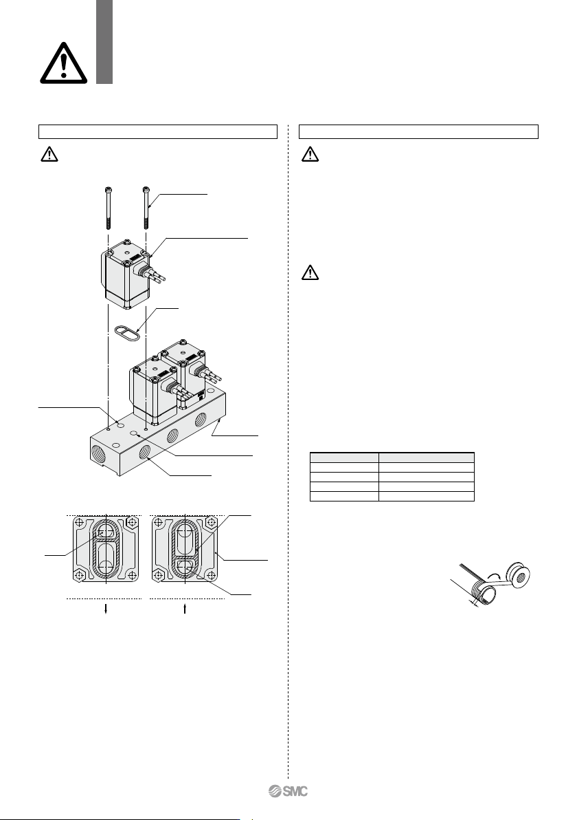
5. Winding of sealant tape
When connecting pipes, fittings,
etc., be sure that chips from the
pipe threads and sealing material
do not enter the valve.
Furthermore, when sealant tape is
used, leave 1.5 to 2 thread ridges
exposed at the end of the threads.
6. In applications such as vacuum and non-leak speci-
fications, use caution specifically against the
contamination of foreign objects or airtightness of
the fittings.
Tightening Torque for Piping
Thread size
Rc1/8
Rc1/4
Rc3/8
Rc1/2
7 to 9
12 to 14
22 to 24
28 to 30
Proper tightening torque (N·m)
Individual SUP
for medium vacuum
Common SUP
for air
Manifold Exploded View
IN port (Common SUP)
OUT port (Individual SUP)
IN port
Gasket
IN port
Solenoid valve for manifold
Gasket
Mounting screw
OUT port (Common SUP)
IN port (Individual SUP)
Individual port sideIndividual port side
∗ Mounting orientation exists when mounting valves onto manifold base.
Mount it as shown above.
∗ Take great care when special electrical entry direction (XC) is used.
Individual port
Solenoid valve
interface for
manifold
Manifold base
VX21/22/23 Series
Specific Product Precautions 4
Be sure to read this before handling the products.
Refer to back page 50 for Safety Instructions and pages 17 to 19 for 2 Port Solenoid
Valve for Fluid Control Precautions.
Winding
direction
Sealant tape
Expose approx.
2 threads
76
Wiring
Caution
1. As a rule, use electrical wire with a cross sectional
area of 0.5 to 1.25 mm
2
for wiring.
Furthermore, do not allow excessive force to be ap-
plied to the lines.
2. Use electrical circuits which do not generate chatter-
ing in their contacts.
3. Use voltage which is within ±10% of the rated volt-
age. In cases with a DC power supply where impor-
tance is placed on responsiveness, stay within ±5%
of the rated value. The voltage drop is the value in
the lead wire section connecting the coil.
4. When a surge from the solenoid affects the electrical
circuitry, install a surge voltage suppressor etc., in
parallel with the solenoid. Or, adopt an option that
comes with the surge voltage protection circuit.
(However, a surge voltage occurs even if the surge
voltage protection circuit is used.)
Warning
1. The solenoid valve is an electrical product. For safety,
install an appropriate fuse and circuit breaker before
use.
When using multiple solenoid valves, it is not sufficient to
merely install one fuse on the inlet side. In order to ensure the
safety of the devices, select and install a fuse for each circuit.
2. Do not apply AC voltage to Class “H” coil AC type
unless it is built in full-wave rectifier, or the coil will
be damaged.
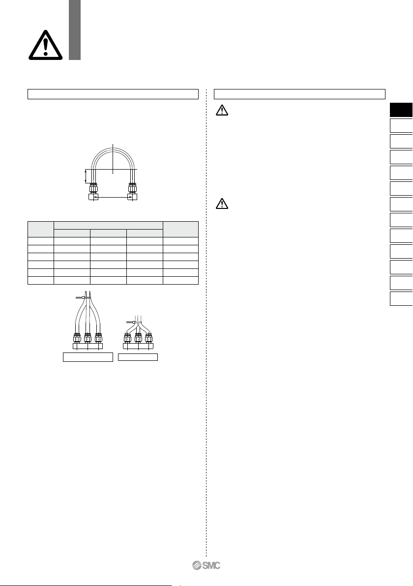
Recommended
Unacceptable
Fig. 2 Binding tubes with bands
Straight
portion
Mounting
pitch
A
Fig. 1 Recommended piping configuration
Recommended Piping Conditions
1. When connecting tubes using One-touch fittings,
provide some spare tube length shown in Fig. 1, rec-
ommended piping configuration.
Also, do not apply external force to the fittings when binding
tubes with bands etc. (see Fig. 2.)
Tube
size
Mounting pitch
A
Unit: mm
Nylon tubing
Soft nylon tubing
Polyurethane tubing
44 or more
84 or more
89 or more
112 or more
140 or more
168 or more
29 or more
39 or more
56 or more
58 or more
70 or more
82 or more
25 or more
39 or more
57 or more
52 or more
69 or more
88 or more
Straight
portion length
ø1/8"
ø6
ø1/4"
ø8
ø10
ø12
16 or more
30 or more
32 or more
40 or more
50 or more
60 or more
VX21/22/23 Series
Specific Product Precautions 5
Be sure to read this before handling the products.
Refer to back page 50 for Safety Instructions and pages 17 to 19 for 2 Port Solenoid
Valve for Fluid Control Precautions.
77
VX2
VXK
VXD
VXZ
VXS
VXB
VXE
VXP
VXR
VXH
VXF
VX3
VXA
VX2
C