6-9-p0027-0080-vx21_en.pdf - 第46页
VX21/22/23 Series Example 1) Obtain the pressure difference when water [15 L/min] runs through the solenoid valv e with a Kv = 1.5 m 3 /h. As the flow rate when Kv = 1 is calculated as the formula: Q 0 = 15 x 1/1.5 = 10 …
2.3 Flow coefficient Cv factor
The United States Standard ANSI/(NFPA)T3.21.3: R1-2008R: Pneumatic fluid power—Flow rating test
procedure and reporting method for fixed orifice components
This standard defines the Cv factor of the flow coefficient by the following formula that is based on the test
conducted by the test circuit analogous to ISO 6358.
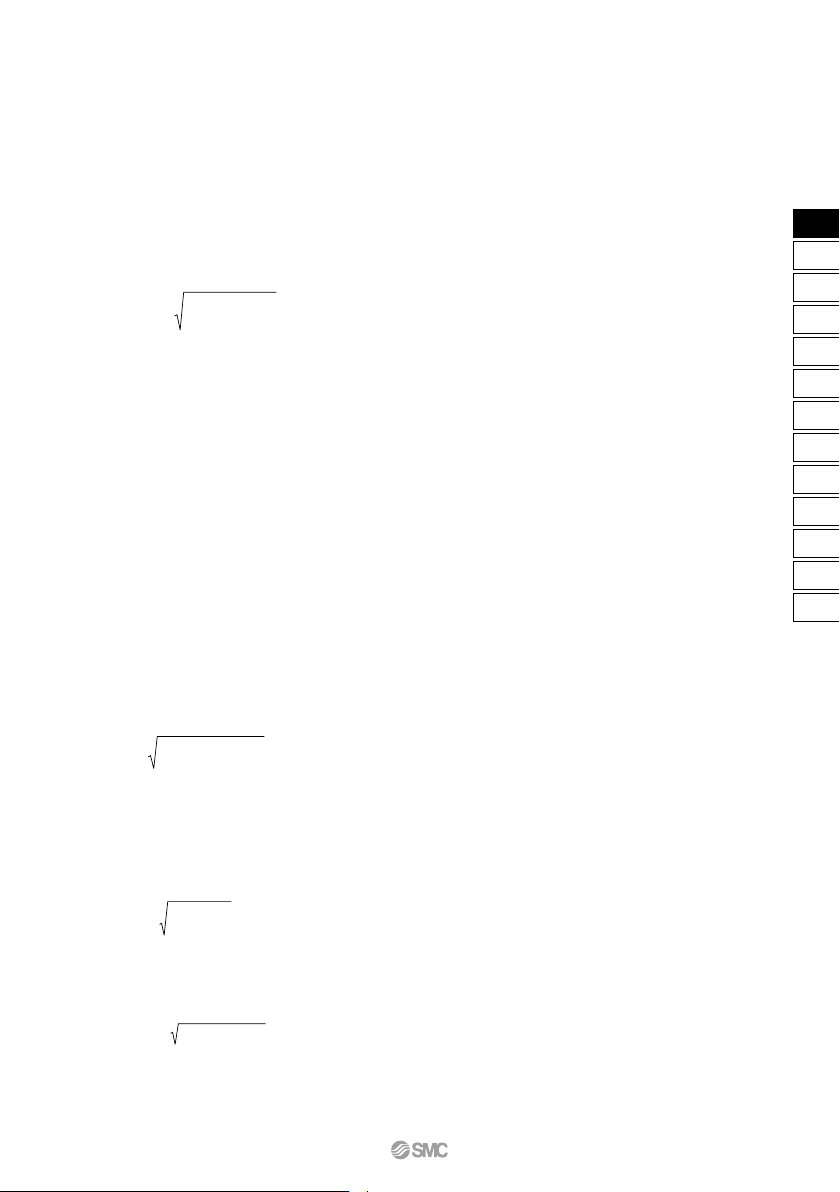
Q
Cv
= ———————————
·········································································(7)
∆P (P2 + Pa)
114.5
——————
T1
∆P
: Pressure drop between the static pressure tapping ports [bar]
P1
: Pressure of the upstream tapping port [bar gauge]
P2
: Pressure of the downstream tapping port [bar gauge]:P2 = P1 – ∆P
Q
: Flow rate [L/s standard condition]
Pa
: Atmospheric pressure [bar absolute]
T1
: Upstream absolute temperature [K]
Test conditions are < P1 + Pa = 6.5 ± 0.2 bar absolute, T1 = 297 ± 5K, 0.07 bar ≤ ∆P � 0.14 bar.
This is the same concept as effective area A which ISO 6358 stipulates as being applicable only when the
pressure drop is smaller than the upstream pressure and the compression of air does not become a problem.
3. Process fluid control equipment
(1) Conformed standard
IEC60534-1: 2005: Industrial-process control valves. Part 1: control valve terminology and
general considerations
IEC60534-2-3: 1997: Industrial-process control valves. Part 2: Flow capacity, Section Three-
Test procedures
JIS B 2005-1: 2012:
Industrial-process control valves – Part 1: Control valve terminology and general considerations
JIS B 2005-2-3: 2004:
Industrial-process control valves – Part 2: Flow capacity – Section 3: Test procedures
Equipment standards: JIS B 8471: Solenoid valve for water
JIS B 8472: Solenoid valve for steam
JIS B 8473: Solenoid valve for fuel oil
(2) Definition of flow rate characteristics
Kv factor:
Value of the clean water flow rate represented by m
3
/h that runs through the valve (equipment for test) at
5 to 40°C, when the pressure difference is 1 x 10⁵ Pa (1 bar). It is calculated using the following formula:
1 x 10
5
Kv = Q
————
· ——— ········································································(8)
∆P 1000
Kv
: Flow coefficient [m
3
/h]
Q
: Flow rate [m
3
/h]
∆P
: Pressure difference [Pa]
: Density of fluid [kg/m
3
]
(3) Formula of flow rate
It is described by the practical units. Also, the flow rate characteristics are shown in Graph (2).
In the case of liquid:
∆P
Q
= 53Kv ———— ···············································································(9)
G
Q
: Flow rate [L/min]
Kv
: Flow coefficient [m
3
/h]
∆P
: Pressure difference [MPa]
G
: Relative density [water = 1]
In the case of saturated aqueous vapor:
Q = 232Kv
∆P(P2 + 0.1) ·······································································(10)
Q
: Flow rate [kg/h]
Kv
: Flow coefficient [m
3
/h]
∆P
: Pressure difference [MPa]
P1
: Upstream pressure [MPa]: ∆P = P1 – P2
P2
: Downstream pressure [MPa]
ρ
ρ
Solenoid Valve Flow Rate Characteristics VX21/22/23 Series
69
VX2
VXK
VXD
VXZ
VXS
VXB
VXE
VXP
VXR
VXH
VXF
VX3
VXA
VX2
VX21/22/23 Series
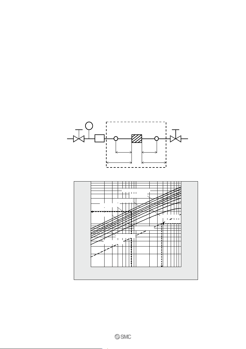
Example 1)
Obtain the pressure difference when water [15 L/min] runs through the solenoid valve with a Kv = 1.5 m
3
/h.
As the flow rate when Kv = 1 is calculated as the formula: Q0 = 15 x 1/1.5 = 10 [L/min], read off ∆P when Q0 is
10 [L/min] in Graph (2). The reading is 0.036 [MPa].
Example 2)
Obtain the saturated steam flow rate when P1 = 0.8 [MPa] and ∆P = 0.008 [MPa] with a solenoid valve
with a Kv = 0.05 [m
3
/h]. Read off Q0 when P1 is 0.8 and ∆P is 0.008 in Graph (2), the reading is 20 kg/h.
Therefore, the flow rate is calculated as the formula: Q = 0.05/1 x 20 = 1 [kg/h].
Conversion of flow coefficient:
Kv = 0.865
Cv ···········································································(11)
Here,
Cv factor: Value of the clean water flow rate represented by US gal/min that runs through the valve at 40 to
100°F, when the pressure difference is 1 lbf/in
2
(psi)
Value is different from
Kv and Cv factors for pneumatic purpose due to different test method.
(4) Test method
Connect the equipment for the test to the test circuit shown in Fig. (3), and run water at 5 to 40°C. Then, measure the flow rate with
a pressure difference where vaporization does not occur in a turbulent flow (pressure difference of 0.035 MPa to 0.075 MPa when
the inlet pressure is within 0.15 MPa to 0.6 MPa). However, as the turbulent flow is definitely caused, the pressure difference needs
to be set with a large enough difference so that the Reynolds number does not fall below 1 x 10⁵, and the inlet pressure needs to
be set slightly higher to prevent vaporization of the liquid. Substitute the measurement results in formula (8) to calculate Kv.
Fig. (3) Test circuit based on IEC60534-2-3, JIS B 2005-2-3
Test range
Equipment
for test
Thermometer
Throttle valve
in the
upstream side
Throttle valve in the
downstream side
Flow
meter
Pressure
tap
2
d
≥ 20d ≥ 7d
6d
Pressure
tap
Water flow rate Q0 [L/min] (When Kv = 1)
Saturated steam flow rate
Q0
[kg/h] (when
Kv
= 1)
Pressure differential
∆P [MPa]
Upstream pressure
P1 = 1 MPa
P1 = 0.8 MPa
P1 = 0.6 MPa
P1 = 0.5 MPa
P1 = 0.1 MPa
P1 = 0.2 MPa
P1 = 0.4 MPa
Example 2
Example 1
P1 = 0.3 MPa
1
10
100
1
10
100
0.001 0.01 0.1
20
3
4
30
20
5
30
0.002 0.003 0.02 0.03 0.040.004
2
3
4
5
2
50
4040
50
Graph (2) Flow rate characteristics
70
VX21/22/23 Series
Flow Rate Characteristics 1
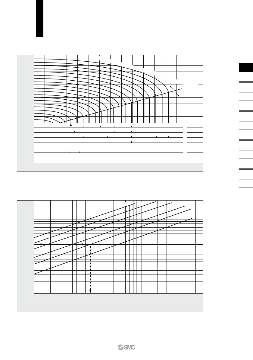
Note) Use this graph as a guide. In the case of obtaining an accurate flow rate, refer to pages 66 through to 70.
How to read the graph
The sonic range pressure to generate a flow rate of 400 L/min (ANR) is P
1
≈ 0.2 MPa for a ø4 orifice and P
1
≈ 0.58 MPa for a ø3 orifice.
How to read the graph
When a water flow of 2 L/min is generated, ∆P ≈ 0.013 MPa for a valve with ø3 orifice.
For Air
Downstream pressure of valve (P2) [MPa]
1.0
0.8
0.6
0.4
0.2
0
ø2
ø3
ø4
ø5
ø7
ø8
ø10 (Connection: 1/4)
ø10 (Connection: 3/8, 1/2)
Flow rate
Q
[L/min (ANR)]
50 100 150 200 250 300 400350
100 200 300 400 500
1,000
400 600
600
800 1,000 1,200
200 1,400
350 700
400 700 1,000 1,300
500 700
700
1,000
Upstream pressure of valve
P
1 ≈ 1.0 MPa
Subsonic
Sonic
Critical
pressure
0.1
0.2
0.3
0.4
0.5
0.6
0.7
0.8
0.9
For Water
Flow rate
Q
[L/min]
30
20
10
5
4
3
2
1
0.1
0.001 (0.0018) (0.0054) 0.01
(0.013)
0.05 (0.07)
Pressure differential ∆P = (P1 − P2) [MPa]
ø4
,
ø5
ø8
ø7
ø3
ø2
ø10
71
VX2
VXK
VXD
VXZ
VXS
VXB
VXE
VXP
VXR
VXH
VXF
VX3
VXA
VX2