6-9-p0027-0080-vx21_en.pdf - 第6页
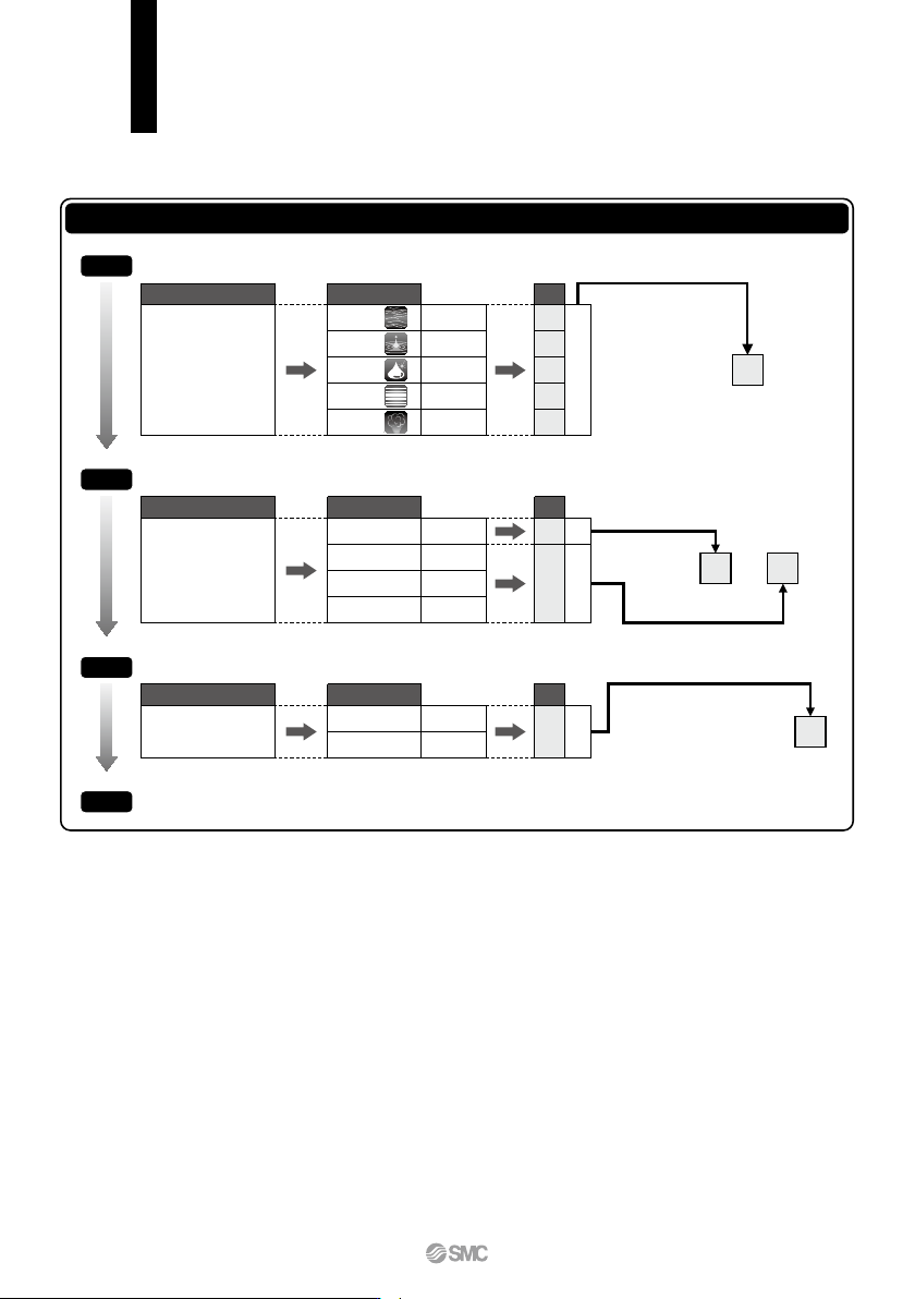
VX21 /22/23 Series Selection Steps Item Select the fluid. Select electrical specification. Selection item Symbol Air Water Oil Medium vacuum 0 2 3 4 5 Symbol 3 A Symbol A Page Page 33, 34 Page 42 Page 44 Page 38 Page 46 …
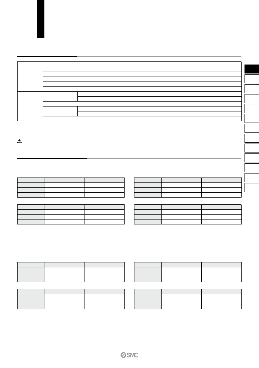
Solenoid Coil Specifications
Size 1
Size 2
Size 3
Size
4.5
7
10.5
Power consumption (W)
Note 1)
50
55
65
Temperature rise (°C)
Note 2)
DC Specification
Note 1) Power consumption: The value at ambient temperature of 20°C
and when the rated voltage is applied. (Variation: ±10%)
Note 2) The value at ambient temperature of 20°C and when the rated
voltage is applied. The value depends on the ambient environ-
ment. This is for reference.
Note 1) Power consumption: The value at ambient temperature of 20°C
and when the rated voltage is applied. (Variation: ±10%)
Note 2) The value at ambient temperature of 20°C and when the rated
voltage is applied. The value depends on the ambient environ-
ment. This is for reference.
Note 1) Apparent power: The value at ambient temperature of 20°C and
when the rated voltage is applied. (Variation: ±10%)
Note 2) There is no difference in the frequency and the inrush and ener-
gized apparent power, since a rectifying circuit is used in the AC.
Note 3) The value at ambient temperature of 20°C and when the rated
voltage is applied. The value depends on the ambient environ-
ment. This is for reference.
Note 1) Apparent power: The value at ambient temperature of 20°C and
when the rated voltage is applied. (Variation: ±10%)
Note 2) There is no difference in the frequency and the inrush and ener-
gized apparent power, since a rectifying circuit is used in the AC.
Note 3) The value at ambient temperature of 20°C and when the rated
voltage is applied. The value depends on the ambient environ-
ment. This is for reference.
Size 1
Size 2
Size 3
Size
7
9.5
12
60
70
70
Apparent power (VA)
Note 1) 2)
Temperature rise (°C)
Note 3)
Class B Class B
Size 1
Size 2
Size 3
Size
9
12
15
100
100
100
Apparent power (VA)
Note 1) 2)
Temperature rise (°C)
Note 3)
Class H
Size 1
Size 2
Size 3
Size
9
12
15
100
100
100
Apparent power (VA)
Note 1) 2)
Temperature rise (°C)
Note 3)
Class H
Size 1
Size 2
Size 3
Size
9
10
14
60
70
70
Apparent power (VA)
Note 1) 2)
Temperature rise (°C)
Note 3)
AC Specification (Built-in Full-wave Rectifier Type)AC Specification (Built-in Full-wave Rectifier Type)
Class B Class B
Normally Closed (N.C.)
Size 1
Size 2
Size 3
Size
7.5
8.5
12.5
Power consumption (W)
Note 1)
60
70
70
Temperature rise (°C)
Note 2)
DC Specification
Normally Open (N.O.)
Size 1
Size 2
Size 3
Size
9
12
15
100
100
100
Power consumption (W)
Note 1)
Temperature rise (°C)
Note 2)
Class H
Size 1
Size 2
Size 3
Size
9
12
15
100
100
100
Power consumption (W)
Note 1)
Temperature rise (°C)
Note 2)
Class H
VX21/22/23 Series
Common Specifications
Standard Specifications
Valve
specifications
Coil
specifications
Valve construction
Withstand pressure
Body material
Seal material
Note 3)
Enclosure
Environment
Rated voltage
Allowable voltage fluctuation
Allowable leakage
voltage
Coil insulation type
Direct operated poppet
2.0 MPa (Resin body type 1.5 MPa)
Aluminum, Resin, C37 (Brass), Stainless steel
NBR, FKM
Dust-tight, Water-jet-proof type (IP65)
Note 1,4)
Location without the presence of corrosive gases, explosive gases, or constant water adhesion
Note 4)
100 VAC, 200 VAC, 110 VAC, 230 VAC, (220 VAC, 240 VAC, 48 VAC, 24 VAC)
Note 2)
24 VDC, (12 VDC)
Note 2)
±10% of rated voltage
5% or less of rated voltage
2% or less of rated voltage
Class B, Class H
AC
DC
Note 1) Electrical entry flat terminal type terminal is IP40.
Note 2) Voltage in ( ) indicates special voltage. (Refer to page 49.)
Note 3) For seal material/EPDM, refer to X332. (Refer to page 51.)
Note 4) For enclosure, refer to “Glossary of Terms” on page 65.
AC
DC
Be sure to read “Specific Product Precautions” before handling.
31
VX2
VXK
VXD
VXZ
VXS
VXB
VXE
VXP
VXR
VXH
VXF
VX3
VXA
VX2
C
VX21/22/23 Series
Selection Steps
Item
Select the fluid.
Select electrical
specification.
Selection item
Symbol
Air
Water
Oil
Medium
vacuum
0
2
3
4
5
Symbol
3
A
Symbol
A
Page
Page 33, 34
Page 42
Page 44
Page 38
Page 46
VX2 3 0 A A
VX2 3 A A0
Size
Body material
Port size
Orifice diameter
Size 3
Aluminum
1/8
2
VX2 3 0 A A
Voltage
Electrical entry
Grommet
24 VDC
Steam
∗
Can be used with heated water.
Select from “Flow
rate — Pressure.”
Body material
Port size
Orifice diameter
Item
Selection item
Item
Selection item
Select the fluid.
Select electrical specification.
For special options, refer to pages 49 to 51.
Select “Body material”, “Port size” and “Orifice diameter” from “Flow rate — Pressure” of each fluid.
Step 1
Step 2
Step 3
Step 4
Selection Steps
q
e
r
r
e
w
w
q
32
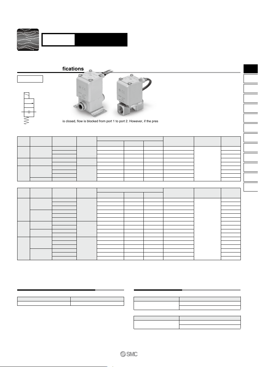
Model/Valve Specifications
N.C.
Port size
Size
Orifice diameter
(mmø)
Note 1)
Model
Maximum operating
pressure differential
(MPa)
Note 4)
1.0
0.6
0.2
1.0
0.15
1.0
0.3
0.1
0.1
2
3
5
4
7
5
8
10
10
1/8, 1/4
1/4, 3/8
1/4, 3/8
1/2
1
2
3
C [dm
3
/(s·bar)]
b
0.23
0.41
0.62
0.62
1.08
0.75
1.58
2.21
2.21
1.0
0.63
0.68
0.39
0.52
0.44
0.55
0.33
0.64
0.39
0.63
1.05
2.20
1.90
3.99
1.96
5.67
5.74
8.42
Cv
Flow rate characteristics
Note 2)
AIuminum Body Type
VX210
VX220
VX230
VX210
VX220
VX230
Port sizeSize
Orifice diameter
(mmø)
Note 1)
Model
Maximum operating
pressure differential
(MPa)
Note 4)
1.0
0.6
0.2
1.0
0.6
0.2
1.0
0.15
1.0
0.15
1.0
0.3
0.1
1.0
0.3
0.1
0.82
1.25
1.45
0.82
1.81
2.11
1.69
3.14
1.68
3.54
2.50
2.77
5.69
2.50
2.56
5.69
2
3
5
2
3
5
4
7
4
7
5
8
10
5
8
10
ø6
ø8
ø8
ø10
ø10
ø12
1
2
3
C [dm
3
/(s·bar)]
b Cv
Flow rate characteristics
Note 2)
Resin Body Type (Built-in One-touch Fittings)
Max. system pressure
(MPa)
Note 4)
Max. system pressure
(MPa)
Note 4)
0.44
0.34
0.43
0.44
0.40
0.32
0.40
0.34
0.49
0.36
0.44
0.82
0.46
0.44
0.88
0.64
0.23
0.35
0.40
0.23
0.41
0.56
0.47
0.84
0.50
0.90
0.70
1.22
1.54
0.70
1.38
1.76
1.0
220
220
220
340
340
450
450
450
470
220
220
220
220
220
220
340
340
340
340
460
460
460
460
460
460
21
When the valve is closed, flow is blocked from port 1 to port 2. However, if the pressure in port 2 is
higher than port 1, the valve will not be able to block the fluid and it will flow from port 2 to port 1.
Direct Operated 2 Port Solenoid Valve
VX21/22/23 Series
For Air Single Unit
Symbol
Note 1) The orifice size is just as a reference guide. Check the flow rate characteristics (conversion Cv).
Note 2) The flow rate characteristics of this product have variations.
When the highly precise flow control is required according to the system to be used, select an orifice diameter 1.3 times larger than that shown
above and install a restrictor on the downstream side of the solenoid valve to make the adjustment.
Note 3) Weight of grommet type. Add 10 g for conduit type, 30 g for DIN terminal type, 60 g for conduit terminal type respectively.
Note 4) Refer to “Glossary of Terms” on page 65 for details on the maximum operating pressure differential and the maximum system pressure.
Fluid and Ambient Temperature
Note) Dew point temperature: −10°C or less
−20 to 60
Ambient temperature (°C)Fluid temperature (°C)
−10
Note)
to 60
Valve Leakage Rate
Internal Leakage
Note 1) Leakage is the value at ambient temperature 20°C.
Note 2) For seal material/FKM, refer to “Other Options” on page 49 for the
selection.
Note 3) The amount of leakage is the value at a differential pressure of
0.01 MPa or more, and a temperature of 20°C.
External Leakage
NBR (FKM)
Seal material
Note 2)
Leakage rate (Air)
Note 1)
1 cm
3
/min or less (AIuminum body type)
15 cm
3
/min or less (Resin body type)
NBR (FKM)
Seal material
Note 2)
Leakage rate (Air)
Note 1)
1 cm
3
/min or less (AIuminum body type)
15 cm
3
/min or less (Resin body type)
Weight
(g)
Note 3)
Weight
(g)
Note 3)
33
VX2
VXK
VXD
VXZ
VXS
VXB
VXE
VXP
VXR
VXH
VXF
VX3
VXA
VX2
B