6-9-p0027-0080-vx21_en.pdf - 第53页
Wiring Caution 1. As a rule, use electrical wire with a cross sectional area of 0.5 to 1.25 mm 2 for wiring. Furthermore, do not allow excessive force to be ap- plied to the lines. 2. Use electrical circuits which do not…
Disassembly/Assembly Procedures
Caution
Piping
Warning
Caution
1. During use, deterioration of the tube or damage to
the fittings could cause tubes to come loose from
their fittings and thrash about.
To prevent uncontrolled tube movement, install protective
covers or fasten tubes securely in place.
2. For piping the tube, fix the product securely using the
mounting holes so that the product is not in the air.
1. Preparation before piping
Before piping is connected, it should be thoroughly blown out
with air (flushing) or washed to remove chips, cutting oil and
other debris from inside the pipe. Avoid pulling, compressing, or
bending the valve body when piping.
2. Avoid connecting ground lines to piping, as this may
cause electric corrosion of the system.
3. Always tighten threads with the proper tightening
torque.
When using steel piping, tighten with the proper tightening
torque shown below.
Lower tightening torque will lead into fluid leakage.
4. Connection of piping to products
When connecting piping to a product, avoid mistakes regarding
the supply port etc.
5. Winding of sealant tape
When connecting pipes, fittings,
etc., be sure that chips from the
pipe threads and sealing material
do not enter the valve.
Furthermore, when sealant tape is
used, leave 1.5 to 2 thread ridges
exposed at the end of the threads.
6. In applications such as vacuum and non-leak speci-
fications, use caution specifically against the
contamination of foreign objects or airtightness of
the fittings.
Tightening Torque for Piping
Thread size
Rc1/8
Rc1/4
Rc3/8
Rc1/2
7 to 9
12 to 14
22 to 24
28 to 30
Proper tightening torque (N·m)
Individual SUP
for medium vacuum
Common SUP
for air
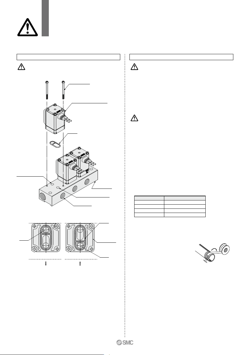
Manifold Exploded View
IN port (Common SUP)
OUT port (Individual SUP)
IN port
Gasket
IN port
Solenoid valve for manifold
Gasket
Mounting screw
OUT port (Common SUP)
IN port (Individual SUP)
Individual port sideIndividual port side
∗ Mounting orientation exists when mounting valves onto manifold base.
Mount it as shown above.
∗ Take great care when special electrical entry direction (XC) is used.
Individual port
Solenoid valve
interface for
manifold
Manifold base
VX21/22/23 Series
Specific Product Precautions 4
Be sure to read this before handling the products.
Refer to back page 50 for Safety Instructions and pages 17 to 19 for 2 Port Solenoid
Valve for Fluid Control Precautions.
Winding
direction
Sealant tape
Expose approx.
2 threads
76
Wiring
Caution
1. As a rule, use electrical wire with a cross sectional
area of 0.5 to 1.25 mm
2
for wiring.
Furthermore, do not allow excessive force to be ap-
plied to the lines.
2. Use electrical circuits which do not generate chatter-
ing in their contacts.
3. Use voltage which is within ±10% of the rated volt-
age. In cases with a DC power supply where impor-
tance is placed on responsiveness, stay within ±5%
of the rated value. The voltage drop is the value in
the lead wire section connecting the coil.
4. When a surge from the solenoid affects the electrical
circuitry, install a surge voltage suppressor etc., in
parallel with the solenoid. Or, adopt an option that
comes with the surge voltage protection circuit.
(However, a surge voltage occurs even if the surge
voltage protection circuit is used.)
Warning
1. The solenoid valve is an electrical product. For safety,
install an appropriate fuse and circuit breaker before
use.
When using multiple solenoid valves, it is not sufficient to
merely install one fuse on the inlet side. In order to ensure the
safety of the devices, select and install a fuse for each circuit.
2. Do not apply AC voltage to Class “H” coil AC type
unless it is built in full-wave rectifier, or the coil will
be damaged.
Recommended
Unacceptable
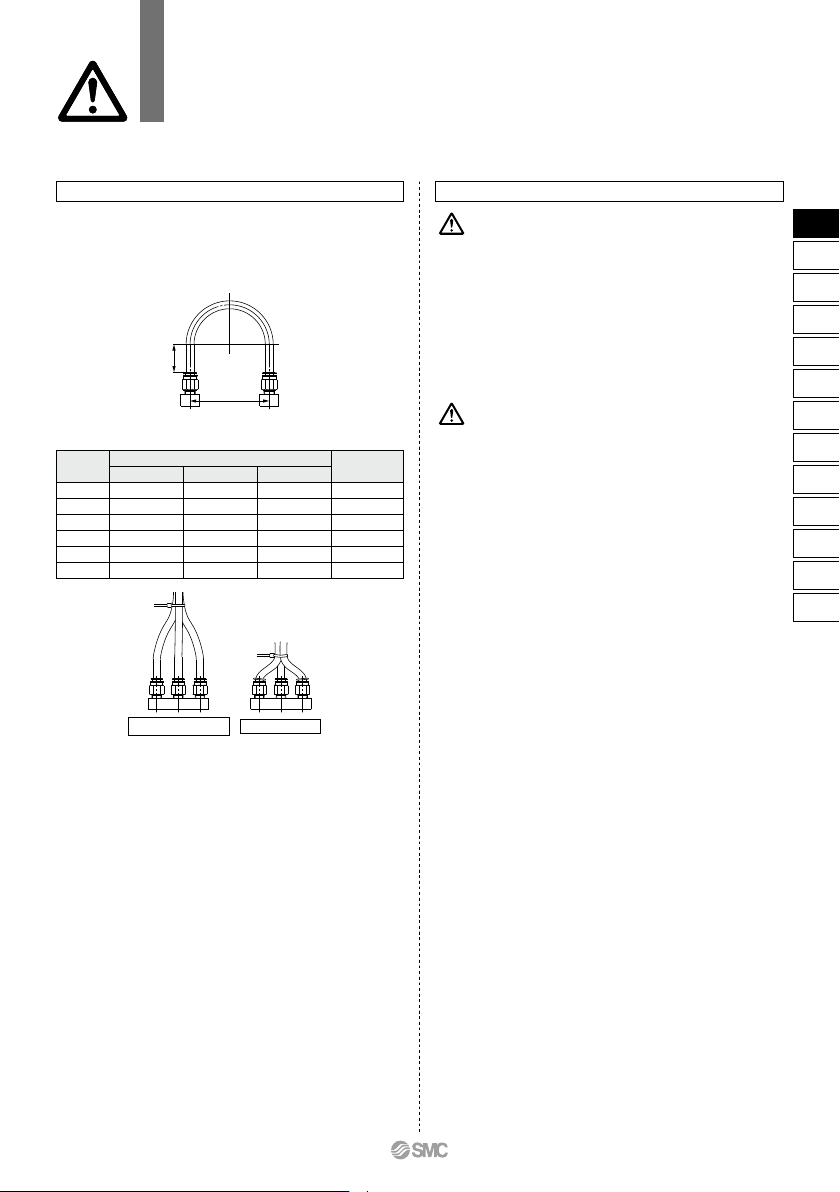
Fig. 2 Binding tubes with bands
Straight
portion
Mounting
pitch
A
Fig. 1 Recommended piping configuration
Recommended Piping Conditions
1. When connecting tubes using One-touch fittings,
provide some spare tube length shown in Fig. 1, rec-
ommended piping configuration.
Also, do not apply external force to the fittings when binding
tubes with bands etc. (see Fig. 2.)
Tube
size
Mounting pitch
A
Unit: mm
Nylon tubing
Soft nylon tubing
Polyurethane tubing
44 or more
84 or more
89 or more
112 or more
140 or more
168 or more
29 or more
39 or more
56 or more
58 or more
70 or more
82 or more
25 or more
39 or more
57 or more
52 or more
69 or more
88 or more
Straight
portion length
ø1/8"
ø6
ø1/4"
ø8
ø10
ø12
16 or more
30 or more
32 or more
40 or more
50 or more
60 or more
VX21/22/23 Series
Specific Product Precautions 5
Be sure to read this before handling the products.
Refer to back page 50 for Safety Instructions and pages 17 to 19 for 2 Port Solenoid
Valve for Fluid Control Precautions.
77
VX2
VXK
VXD
VXZ
VXS
VXB
VXE
VXP
VXR
VXH
VXF
VX3
VXA
VX2
C
Electrical Connections
Caution
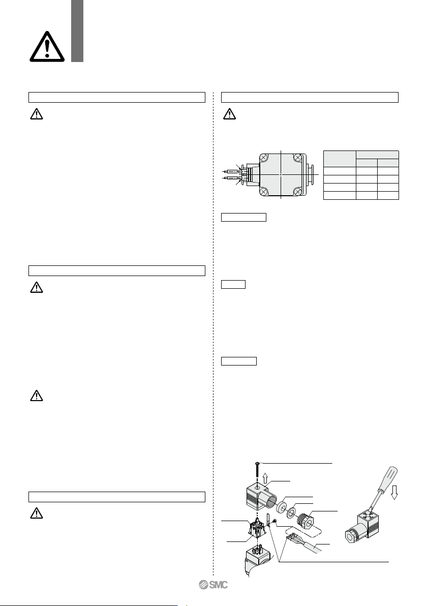
Grommet
Class B coil: AWG20 Insulator O.D. 2.6 mm
Class H coil: AWG18 Insulator O.D. 2.1 mm
Caution
Operating Environment
Warning
1. Be sure to have appropriate protective measures in
place when installed in environments where there is
the constant presence of water, such as water spray,
condensation, high humidity, etc. This product has
an IP65 protective construction; however, when
used in the above-mentioned environments, liquid
may find its way inside the enclosure through micro-
scopic gaps, possibly resulting in the burning out,
short-circuiting, or ignition of coils.
2. Do not use in an atmosphere having corrosive gases,
chemicals, sea water, or where there is direct contact
with any of these.
3. Do not use in explosive atmospheres.
4. Do not use in locations subject to vibration or impact.
5. Do not use in locations where radiated heat will be
received from nearby heat sources.
6. Employ suitable protective in locations where there
is contact with oil or welding spatter, etc.
Maintenance
Warning
1. Filters and strainers
1) Be careful regarding clogging of filters and strainers.
2) Replace filter elements after one year of use, or earlier if the
pressure drop reaches 0.1 MPa.
3) Clean strainers when the pressure drop reaches 0.1 MPa.
2. Lubrication
When using after lubricating, never forget to lubricate continuously.
3. Storage
In case of long term storage after use, thoroughly remove all
moisture to prevent rust and deterioration of rubber materials etc.
4. Exhaust the drainage from an air filter periodically.
1. Removing the product
The valve will reach a high temperature when used with high
temperature fluids. Confirm that the valve temperature has
dropped sufficiently before performing work. If touched inadver-
tently, there is a danger of being burned.
1) Shut off the fluid supply and release the fluid pressure in the
system.
2) Shut off the power supply.
3) Dismount the product.
2. Low frequency operation
Switch valves at least once every 30 days to prevent malfunc-
tion. Also, in order to use it under the optimum state, conduct a
regular inspection once a half year.
Operating Precautions
Warning
1.
If there is a possibility of reverse pressure being applied
to the valve, take countermeasures such as mounting a
check valve on the downstream side of the valve.
2. When problems are caused by a water hammer, in-
stall water hammer relief equipment (accumulator
etc.), or use an SMC water hammer relief valve (VXR
series).
VX21/22/23 Series
Specific Product Precautions 6
Be sure to read this before handling the products.
Refer to back page 50 for Safety Instructions and pages 17 to 19 for 2 Port Solenoid
Valve for Fluid Control Precautions.
q
w
DIN terminal
Disassembly
1. After loosening the binding head screw with flange, then if the
housing is pulled in the direction of the arrow, the connector will
be removed from the solenoid valve.
2. Pull out the binding head screw with flange from the housing.
3. There is a cutout on the bottom of the terminal block. Insert a
small flat head screwdriver, etc. into this cutout, and remove the
terminal block from the housing. (See figure below.)
4.
Remove the ground nut, and pull out the washer and the rubber seal.
Wiring
1. Pass the cable through the ground nut, washer and rubber seal
in this order, and insert these parts into the housing.
2. Loosen the binding head screw of the terminal block, then insert
the core wire or the crimped terminal of the lead wire into the
terminal, and securely fix it with the binding head screw. The
binding head screw of the terminal block is M3.
Note 1)
Tighten the screw to a torque of between 0.5 and 0.6 N·m.
Note 2) Cable O.D.: ø6 to ø12 mm
Note 3) For an outside cable diameter of ø9 to 12 mm, remove
the internal parts of the rubber seal before using.
Assembly
1. Pass the cable through the ground nut, washer, rubber seal and
the housing in this order, and connect to the terminal block.
Then, set the terminal block inside the housing. (Push in the
terminal block until it snaps into position.)
2. Insert the rubber seal and the washer in this order into the cable
entry of the housing, and then tighten the ground nut securely.
3.
Insert the gasket between the bottom part of the terminal block and
the plug attached to the equipment, and then insert the binding
head screw with flange from the top of the housing, and tighten it.
Note 1)
Tighten the screw to a torque of between 0.5 and 0.6 N·m.
Note 2)
The orientation of the connector can be changed in steps
of 90° by changing the method of assembling the housing
and the terminal block.
Rated
voltage
DC
100 VAC
200 VAC
Other AC
q
Black
Blue
Red
Gray
w
Red
Blue
Red
Gray
Lead wire color
∗ There is no polarity.
Housing
Crimped terminal
Applicable crimped terminal: JIS C2805 R1.25-3
Ground nut
Washer
Cable
Rubber seal
Binding head screw with flange
Light (When
equipped
with a light)
∗
1
Terminal
block
∗1
The position is fixed regardless of the electrical entry direction.
Binding
head screw
78
E