6-9-p0027-0080-vx21_en.pdf - 第48页
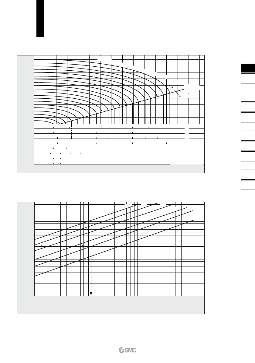
VX21 /22/23 Series Flow Rate Characteristics 2 Note) Use this graph as a guide. In the case of obtaining an accurate flow rate, refer to pages 66 through to 70. For Saturated Steam How to read the graph The sonic range p…
VX21/22/23 Series
Flow Rate Characteristics 1
Note) Use this graph as a guide. In the case of obtaining an accurate flow rate, refer to pages 66 through to 70.
How to read the graph
The sonic range pressure to generate a flow rate of 400 L/min (ANR) is P
1
≈ 0.2 MPa for a ø4 orifice and P
1
≈ 0.58 MPa for a ø3 orifice.
How to read the graph
When a water flow of 2 L/min is generated, ∆P ≈ 0.013 MPa for a valve with ø3 orifice.
For Air
Downstream pressure of valve (P2) [MPa]
1.0
0.8
0.6
0.4
0.2
0
ø2
ø3
ø4
ø5
ø7
ø8
ø10 (Connection: 1/4)
ø10 (Connection: 3/8, 1/2)
Flow rate
Q
[L/min (ANR)]
50 100 150 200 250 300 400350
100 200 300 400 500
1,000
400 600
600
800 1,000 1,200
200 1,400
350 700
400 700 1,000 1,300
500 700
700
1,000
Upstream pressure of valve
P
1 ≈ 1.0 MPa
Subsonic
Sonic
Critical
pressure
0.1
0.2
0.3
0.4
0.5
0.6
0.7
0.8
0.9
For Water
Flow rate
Q
[L/min]
30
20
10
5
4
3
2
1
0.1
0.001 (0.0018) (0.0054) 0.01
(0.013)
0.05 (0.07)
Pressure differential ∆P = (P1 − P2) [MPa]
ø4
,
ø5
ø8
ø7
ø3
ø2
ø10
71
VX2
VXK
VXD
VXZ
VXS
VXB
VXE
VXP
VXR
VXH
VXF
VX3
VXA
VX2
VX21/22/23 Series
Flow Rate Characteristics 2
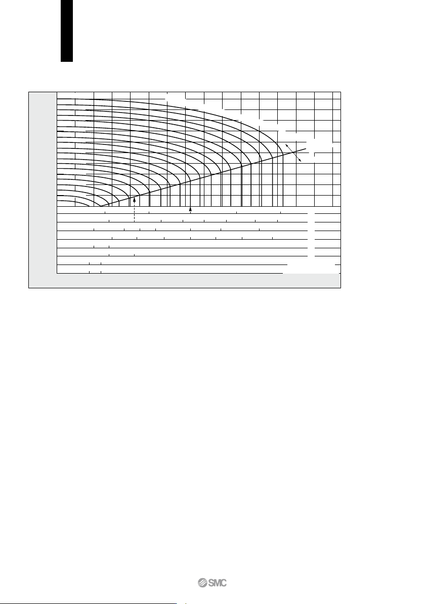
Note) Use this graph as a guide. In the case of obtaining an accurate flow rate, refer to pages 66 through to 70.
For Saturated Steam
How to read the graph
The sonic range pressure to generate a flow rate of 15 kg/h is P1 ≈ 0.55 MPa for a ø2 orifice and P1 ≈ 0.28 MPa for a ø3 orifice.
1.0
0.8
0.6
0.4
0.2
0
0.1
(664)(183)
(663)(179)
(662)(174)
(661)(170)
(660)(164)
(658)(158)
(656)(151)
(654)(143)
(650)(133)
(646)(120)
0.2
0.3
0.4
0.5
0.6
0.7
0.8
0.9
5 10 15 25
20
10 15 20 25 45
403530
40
2010 30
30
40 50 60
50 60 70 80
20 30
20
40 60
30 45
35 50
Downstream pressure of valve (P2) [MPa]
Flow rate
Q
[kg/h]
Upstream pressure of valve
P
1
≈ 1.0 MPa
Subsonic
Sonic
ø2
ø3
ø4
ø5
ø7
ø8
ø10 (Connection: 1/4)
ø10 (Connection: 3/8, 1/2)
Critical
pressure
72
VX21/22/23 Series
Specific Product Precautions 1
Be sure to read this before handling the products.
Refer to back page 50 for Safety Instructions and pages 17 to 19 for 2 Port Solenoid
Valve for Fluid Control Precautions.
Design
Warning
Selection
Warning
1. Cannot be used as an emergency shutoff valve etc.
The valves presented in this catalog are not designed for safety
applications such as an emergency shutoff valve. If the valves
are used in this type of system, other reliable safety assurance
measures should also be adopted.
2. Extended periods of continuous energization
The solenoid coil will generate heat when continuously ener-
gized. Avoid using in a tightly shut container. Install the valve in
a well-ventilated area. Furthermore, do not touch it while it is be-
ing energized or right after it has been energized.
3. Closed liquid circuit
In a closed circuit, when liquid is static, pressure could rise due
to changes in temperature. This pressure rise could cause mal-
function and damage to components such as valves. To pre-
vent this, install a relief valve in the system.
4. Actuator drive
When an actuator, such as a cylinder, is to be driven using a
valve, take appropriate measures to prevent potential danger
caused by actuator operation.
5. Pressure (including vacuum) holding
It is not usable for an application such as holding the pressure
(including vacuum) inside of a pressure vessel because air
leakage is entailed in a valve.
6. When the conduit type is used as equivalent to an
IP65 enclosure, install a wiring conduit etc.
7. When an impact, such as water hammer etc., caused
by the rapid pressure fluctuation is applied, the sole-
noid valve may be damaged. Give an attention to it.
Selection
Warning
1. Fluid
1) Type of fluid
Before using a fluid, check whether it is compatible with the
materials of each model by referring to the fluids listed in this
catalog. Use a fluid with a kinematic viscosity of 50 mm
2
/s or
less.
2) Flammable oil, Gas
Do not use the product with combustion-supporting or flam-
mable fluids.
3) Corrosive gas
Cannot be used since it will lead to cracks by stress corrosion
or result in other incidents.
4) When a brass body is used, then depending on water quality,
corrosion and internal leakage may occur. If such abnormali-
ties occur, exchange the product for a stainless steel body.
5) Use an oil-free specification when any oily particle must not
enter the passage.
6) Applicable fluid on the list may not be used depending on the
operating condition. Give adequate confirmation, and then
determine a model, just because the compatibility list shows
the general case.
2. Fluid quality
<Air>
1) Use clean air.
Do not use compressed air that contains chemicals, synthetic
oils including organic solvents, salt or corrosive gases, etc.,
as it can cause damage or malfunction.
2) Install an air filter.
Install air filters close to the valves on the upstream side. A fil-
tration degree of 5 µm or less should be selected.
3) Install an aftercooler or air dryer, etc.
Compressed air that contains excessive drainage may cause
malfunction of valves and other pneumatic equipment. To
prevent this, install an aftercooler or air dryer, etc.
4) If excessive carbon powder is generated, eliminate it by
installing mist separators at the upstream side of valves.
If excessive carbon powder is generated by the compressor,
it may adhere to the inside of the valves and cause a mal-
function.
Refer to Best Pneumatics No.5 for further details on com-
pressed air quality.
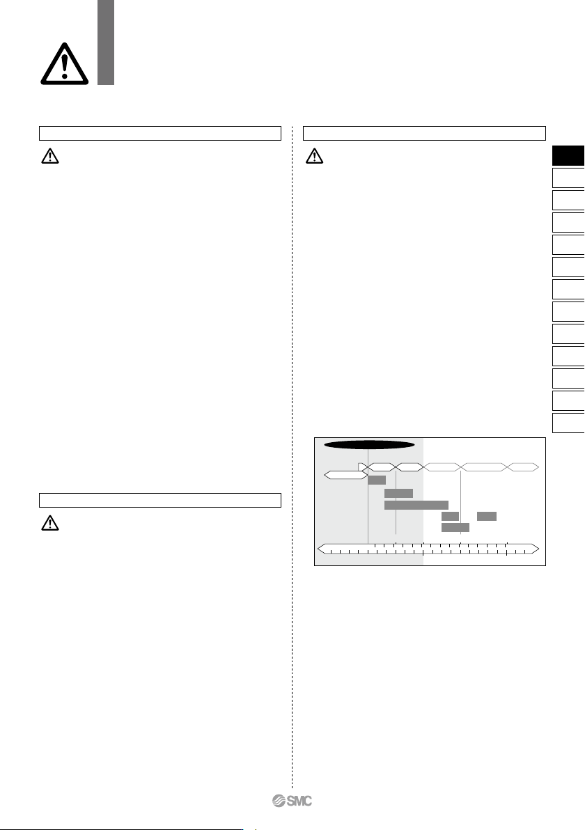
<Vacuum>
Please be aware that there is a range of pressure that can be
used.
Vacuum piping direction: if the system uses a vacuum pump, we
ask that you install the vacuum pump on the secondary side.
Also, install a filter on the primary side, and be careful that no
foreign object is picked up.
Please replace the valve after operating the device approxi-
mately 300,000 times.
Atmospheric pressure
Air pressure
Hydraulic pressure
Low
vacuum
Medium
vacuum
High
vacuum
Ultra high
vacuum
Extreme
high
vacuum
10
-12
10
-11
10
-10
10
-9
10
-8
10
-7
10
-6
10
-5
10
-4
10
-3
10
-2
10
-1
11010
2
10
-12
10
-11
10
-10
10
-9
10
-8
10
-7
10
-6
10
-5
10
-4
10
-3
10
-2
10
-1
110
1
10
2
10
3
10
4
10
5
10
6
10
7
10
8
10
9
Pa
Torr
(mmHg)
Differential
pressure
Drying
Discharge/Plasma
Vapor
deposition
<Accelerator, Electron microscope>
Surface
physics
Charged
particle beam
<Suction filtration, Vacuum bottle set, Suction cup>
Neon tube/Fluorescent light
73
VX2
VXK
VXD
VXZ
VXS
VXB
VXE
VXP
VXR
VXH
VXF
VX3
VXA
VX2
D