6-9-p0027-0080-vx21_en.pdf - 第43页
ø d 2 ø d 1 3 d 3 3 d 2 10 d 2 3 d 1 10 d 1 ≥ 10 d 3 ø d 3 ≥ 3 d 1 Q : Air flow rate [L/min (ANR)] C : Sonic conductance [dm 3 /(s·bar)], dm 3 (Cubic decimeter) of SI = L (liter). b : Critical pressure ratio [—] P 1 : Up…
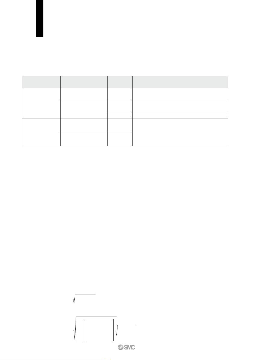
C, b
Indication by
international standard
S
Cv
Cv
Conformed standard
ISO 6358: 1989
JIS B 8390: 2000
JIS B 8390: 2000
Equipment: JIS B 8379, 8381-1, 8381-2
IEC60534-1: 2005
IEC60534-2-3: 1997
JIS B 2005-1: 2012
JIS B 2005-2-3: 2004
Equipment: JIS B 8471, 8472, 8473
ANSI/(NFPA)T3.21.3 R1-2008
Table (1) Indication of Flow Rate Characteristics
Kv
—
—
—
—
Pneumatic
equipment
Process fluid
control
equipment
Corresponding
equipment
Other
indications
1.
Indication of flow rate characteristics
The flow rate characteristics in equipment such as a solenoid valve, etc. are indicated in their specifications as
shown in Table (1).
2.
Pneumatic equipment
2.1 Indication according to the international standards
(1) Conformed standard
ISO 6358: 1989
: Pneumatic fluid power—Components using compressible fluids—
Determination of flow rate characteristics
JIS B 8390: 2000 : Pneumatic fluid power—Components using compressible fluids—
How to test flow rate characteristics
(2) Definition of flow rate characteristics
The flow rate characteristics are indicated as a result of a comparison between sonic conductance C and
critical pressure ratio b.
Sonic conductance C
:
Value which divides the passing mass flow rate of an equipment in a choked flow
condition by the product of the upstream absolute pressure and the density in a
standard condition.
Critical pressure ratio
b : Pressure ratio (downstream pressure/upstream pressure) which will turn to a choked
flow when the value is smaller than this ratio.
Choked flow : The flow in which the upstream pressure is higher than the downstream pressure and
where sonic speed in a certain part of an equipment is reached.
Gaseous mass flow rate is in proportion to the upstream pressure and not dependent
on the downstream pressure.
Subsonic flow : Flow greater than the critical pressure ratio
Standard condition
: Air in a temperature state of 20°C, absolute pressure 0.1 MPa (= 100 kPa = 1 bar),
relative humidity 65%.
It is stipulated by adding the “(ANR)” after the unit depicting air volume.
(standard reference atmosphere)
Conformed standard: ISO 8778: 1990 Pneumatic fluid power—Standard reference
atmosphere, JIS B 8393: 2000: Pneumatic fluid power—Standard reference atmosphere
(3) Formula for flow rate
It is described by the practical units as following.
When
P2 + 0.1
————
≤ b, choked flow
P1 + 0.1
293
Q = 600 x C (P1 + 0.1)
————
·····························································(1)
273 + T
When
P2 + 0.1
———— > b, subsonic flow
P1 + 0.1
P2 + 0.1
———— – b
P1 + 0.1
Q = 600 x C (P1 + 0.1) 1 –
—————— ———— ····························
(2)
1 – b
2
293
273 + T
VX21/22/23 Series
Solenoid Valve Flow Rate Characteristics
(How to indicate flow rate characteristics)
66
ød2
ød1
3d3
3d210d23d110d1≥10d3
ød3≥3d1
Q
: Air flow rate [L/min (ANR)]
C
: Sonic conductance [dm
3
/(s·bar)], dm
3
(Cubic decimeter) of SI = L (liter).
b
: Critical pressure ratio [—]
P1
: Upstream pressure [MPa]
P2
: Downstream pressure [MPa]
T
: Temperature [°C]
Note) Formula of subsonic flow is the elliptic analogous curve.
Flow
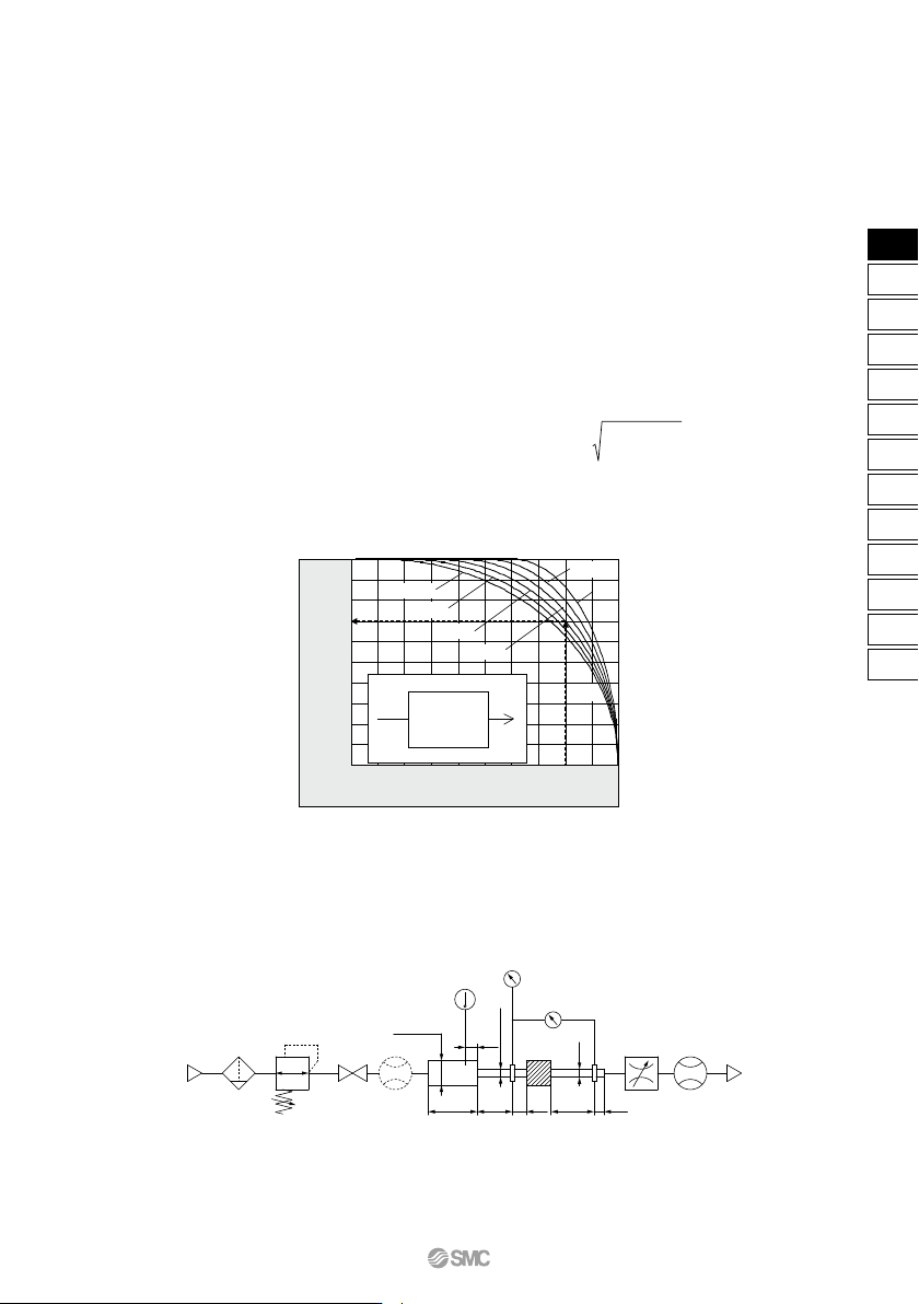
rate characteristics are shown in Graph (1) For details, please use the calculation software available from SMC website.
Example)
Obtain the air flow rate for P1 = 0.4 [MPa], P2 = 0.3 [MPa], T = 20 [°C] when a solenoid valve is performed in
C = 2 [dm
3
/(s·bar)] and b = 0.3.
293
According to formula 1, the maximum flow rate = 600 x 2 x (0.4 + 0.1) x ————— = 600 [L/min (ANR)]
273 + 20
0.3 + 0.1
Pressure ratio = ————— = 0.8
0.4 + 0.1
Based on Graph (1), it is going to be 0.7 if it is read by the pressure ratio as 0.8 and the flow ratio to be b = 0.3.
Hence, flow rate = Max. flow x flow ratio = 600 x 0.7 = 420 [L/min (ANR)]
(4) Test method
Attach a test equipment with the test circuit shown in Fig. (1) while maintaining the upstream pressure to a
certain level which does not go below 0.3 MPa. Next, measure the maximum flow to be saturated in the first
place, then measure this flow rate at 80%, 60%, 40%, 20% and the upstream and downstream pressure. And
then, obtain the sonic conductance C from this maximum flow rate. In addition, calculate b using each data of
others and the subsonic flow formula, and then obtain the critical pressure ratio b from that average.
1
0.9
0.8
0.7
0.6
0.5
0.4
0.3
0.2
0.1
0
0 0.1 0.2 0.3 0.4 0.5 0.6 0.7 0.8 0.9 1
Equipment
C, b
P2
Q
P1
b = 0.1
0.2
0.5
0.6
0.3
0.4
Pressure ratio (
P2 + 0.1) / (P1 + 0.1)
Air
supply
Pressure control
equipment
Thermometer
Pressure gauge or
pressure convertor
Differential pressure gauge or
differential pressure converter
Flow control
valve
Filter
Pipe for measuring
temperature
Pipe for
measuring
pressure in the
upstream side
Pipe for
measuring
pressure in the
downstream side
Equipment
for test
Shut off
valve
Flow meter
Fig. (1) Test circuit based on ISO 6358: 1989, JIS B 8390: 2000
Graph (1) Flow rate characteristics
Flow rate ratio
Example
67
Solenoid Valve Flow Rate Characteristics
VX21/22/23 Series
VX2
VXK
VXD
VXZ
VXS
VXB
VXE
VXP
VXR
VXH
VXF
VX3
VXA
VX2
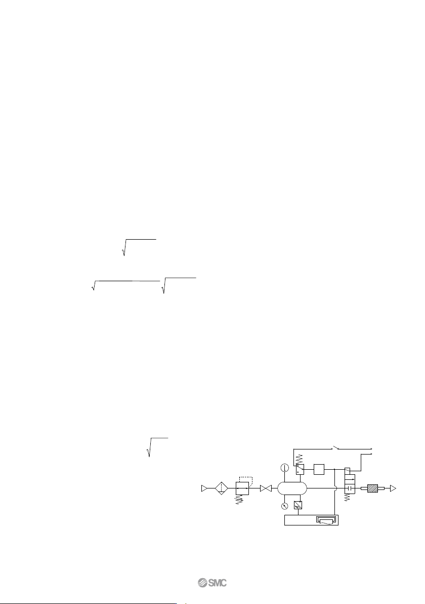
Fig. (2) Test circuit based on JIS B 8390: 2000
Pressure switch
Timer (Clock)
Pressure recorder
Control
circuit
Thermometer
Air tank
Pressure control
equipment
Shut off
valve
FilterAir
supply
Rectifier tube in the
downstream side
Rectifier tube in the
upstream side
Power
supply
Solenoid valve
Equipment
for test
Pressure gauge
or pressure
convertor
2.2 Effective area S
(1) Conformed standard
JIS B 8390: 2000: Pneumatic fluid power—Components using compressible fluids—
Determination of flow rate characteristics
Equipment standards:
JIS B 8373: Solenoid valve for pneumatics
JIS B 8379: Silencer for pneumatics
JIS B 8381-1: Fittings for pneumatics—Part 1: Push-in fittings for thermoplastic resin tubing
JIS B 8381-2: Fittings for pneumatics—Part 2: Compression fittings for thermoplastic resin tubing
(2) Definition of flow rate characteristics
Effective area S
:
The cross-sectional area having an ideal throttle without friction deduced from the calcula-
tion of the pressure changes inside an air tank or without reduced flow when discharging
the compressed air in a choked flow, from an equipment attached to the air tank. This is the
same concept representing the “easy to run through” as sonic conductance C.
(3) Formula for flow rate
When
P2 + 0.1
———— � 0.5, choked flow
P1 + 0.1
293
Q = 120 x S (P1 + 0.1) ————
··································································(3)
273 + T
When
P2 + 0.1
———— > 0.5, subsonic flow
P1 + 0.1
293
Q = 240 x S (P2 + 0.1) (P1 – P2) ————
··············································(4)
273 + T
Conversion with sonic conductance C:
S = 5.0 x C·······································································································(5)
Q
: Air flow rate[L/min(ANR)]
S
: Effective area [mm
2
]
P1 : Upstream pressure [MPa]
P2 : Downstream pressure [MPa]
T
: Temperature [°C]
Note) Formula for subsonic flow (4) is only applicable when the critical pressure ratio b is the unknown
equipment. In the formula (2) by the sonic conductance C, it is the same formula as when b = 0.5.
(4) Test method
Attach a test equipment with the test circuit shown in Fig. (2) in order to discharge air into the atmosphere
until the pressure inside the air tank goes down to 0.25 MPa (0.2 MPa) from an air tank filled with the
compressed air at a certain pressure level (0.5 MPa) which does not go below 0.6 MPa. At this time, measure
the discharging time and the residual pressure inside the air tank which had been left until it turned to be the
normal values to determine the effective area S, using the following formula. The volume of an air tank should
be selected within the specified range by corresponding to the effective area of an equipment for test. In the
case of JIS B 8379, the pressure values are in parentheses and the coefficient of the formula is 12.9.
V Ps + 0.1 293
S = 12.1 — log10 (—————) —— ·················(6)
t P + 0.1
T
S
: Effective area [mm
2
]
V
: Air tank capacity [L]
t
: Discharging time [s]
Ps
: Pressure inside air tank
before discharging [MPa]
P
: Residual pressure inside air tank
after discharging [MPa]
T
: Temperature inside air tank
before discharging [K]
68
VX21/22/23 Series