6-9-p0027-0080-vx21_en.pdf - 第39页
U side 7 6 5 4 3 2 D side Stations 1 2 x 3/8 <Common port> IN port (For common SUP type) OUT port (For individual SUP type) n x 1/8,1/4 <Individual port> OUT port (For common SUP type) IN port (For individual…
D
C
R
Y
E
2 x P
Port size
A
1.5
FQ
≈ 40(42)
≈ 300
For steam and heated water
With full-wave rectifier
(AC type only)
B
B
1
D
T
1.5
2 x P
Port size
A
E
Q±2
F
C
B
B
1
S±2
25
R
U
W
M
X
2 x ø5.3
Mounting
hole
U
W
M
2 x ø5.3
Mounting
hole
X
D
G1/2
C
R
2 x P
Port size
A
Y
E
1.5
FQ≈ 280
(42) ≈ 45
23
B
B
1
For steam and heated water
With full-wave rectifier
(AC type only)
U
W
M
X
2 x ø5.3
Mounting
hole
34
Y
32
U
W
M
X
1.5
R
Y C
E
B1
B
A
D
FQ
S
2 x ø5.3
Mounting
hole
2 x
P
Port size
Cable ø6 to ø12
G1/2
(mm)
Conduit terminal
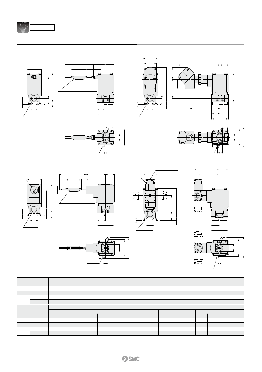
Dimensions/Body Material: C37, Stainless Steel
Grommet
Conduit DIN terminal
Size
1
2
3
A
19
22
22
29.5
B
43
45
45
50
D
30
35
40
40
E
9.5
10.5
10.5
14
F
20
22
24.5
24.5
M
12.8
19
19
—
U
46
56
56
—
W
36
46
46
—
X
11
13
13
—
Y
6
7
7
—
B1 C
21
22.5
22.5
25
61 (67)
74.5 (82.5)
79 (87)
85.5
Port size
P
1/8, 1/4
1/4, 3/8
1/4, 3/8
1/2
Size Grommet
Q
27
29.5
32
32
R
42 (47.5)
53.5 (61.5)
57.5 (65.5)
61
R
36 (41.5)
47 (55)
51.5 (59.5)
55
S Q
77
79.5
82
82
47.5
50
52.5
52.5
T R
77 (83)
89.5 (97.5)
94 (102)
100.5
36 (41.5)
47 (55)
51.5 (59.5)
55
Q
108
110.5
113
113
Conduit terminal Conduit
Electrical entry
Mounting bracket dimensions
1
2
3
Port size
P
1/8, 1/4
1/4, 3/8
1/4, 3/8
1/2
( ): Denotes the Normally Open (N.O.) dimensions.
Flat terminal is not available for valves for steam and heated water.
Q
S
64.5
67
69.5
69.5
52.5
55
57.5
57.5
R
34 (39.5)
45 (53)
49.5 (57.5)
53
DIN terminal
62
VX21/22/23 Series
For Steam
∗ Can be used with heated water.
U side
7
6
5
432
D side
Stations
1
2 x 3/8 <Common port>
IN port (For common SUP type)
OUT port (For individual SUP type)
n x 1/8,1/4 <Individual port>
OUT port (For common SUP type)
IN port (For individual SUP type)
Q6
Q1
Q2
Q5
Q3
Q4 H
L1
L2
K
2 x øM
Mounting
hole
A
J
FP
K
N D
Plug
∗
S2
S1
B
C
G1/2
2532
F
E
D
R1, R6
R5
R2
F
R3
R4
T
(44)
G1/2
G1/2
Cable ø6 to ø12
≈ 280
≈ 300
≈ 300
11
∗ D side port does not have a plug.
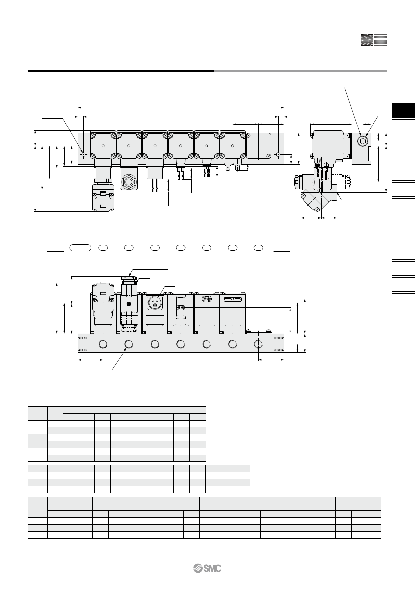
Dimensions/Manifold/Base Material: Aluminum
Size
Dimensions
2 3 4 5 6 7 8 9 10
86
100
90
108
103
121
122
136
126
144
144
162
158
172
162
180
185
203
194
208
198
216
226
244
230
244
234
252
267
285
266
280
270
288
308
326
302
316
306
324
349
367
338
352
342
360
390
408
374
388
378
396
431
449
n (stations)
L1
L2
L1
L2
L1
L2
1
2
3
Size
Grommet DIN terminal
∗
Conduit terminal Conduit Flat terminal
Grommet (With surge
voltage suppressor)
Size
A B C D E F H J K M N P
1
2
3
1
2
3
38
49
49
Q1 R1 Q2 R2 Q3 R3 S1 Q4 R4 S2 T Q5 R5 Q6 R6
27
29.5
32
30
32.5
35
64.5
67
69.5
52.5
55
57.5
68.5
71
73.5
47.5
50
52.5
23
25.5
28
99.5
102
104.5
40.5 (46.5)
49.5 (57.5)
54.5 (63)
32.5 (38.5)
41.5 (49.5)
46.5 (54.5)
34.5 (40.5)
43.5 (51.5)
48.5 (56.5)
66.5 (72)
75.5 (83.5)
80.5 (89.5)
34.5 (40.5)
43.5 (51.5)
48.5 (56.5)
40.5 (46.5)
49.5 (57.5)
54.5 (63)
27 (33)
36 (44)
41 (49)
15.5
18
20.5
10.5
13
13
11
13
13
25
30
30
32
36
40
20
22
24.5
12
15
15
7
9
9
6.5
8.5
8.5
50.5 (56.5)
60.5 (68.5)
65.5 (73.5)
36
36
41
(mm)
( ): Denotes the Normally Open (N.O.) dimensions.
∗ When using a DIN terminal that faces downward, be careful of interference in the electrical wires and piping.
63
Direct Operated 2 Port Solenoid Valve
VX21/22/23 Series
Medium
vacuum
Medium
vacuum
AirAir
VX2
VXK
VXD
VXZ
VXS
VXB
VXE
VXP
VXR
VXH
VXF
VX3
VXA
VX2
¡DIN Connector Part No.
¡Gasket Part No. for DIN Connector
VCW20-1-29-1 (For Class B Coil)
VCW20-1-29-1-F (For Class H Coil)
¡Lead Wire Assembly for Flat Terminal
(Set of 2 pcs.)
VX021S-1-16FB
¡Bracket Assembly Part No. (for Metal Body)
3G-GDM2A-G
GDM2A-L5
GDM2A-L6
GDM2A-L1
GDM2A-L1
GDM2A-L2
GDM2A-L2
GDM2A-L2
GDM2A-L2
GDM2A-L5
GDM2A-L15
Rated voltage
24 VDC
12 VDC
100 VAC
110 VAC
200 VAC
220 VAC
230 VAC
240 VAC
24 VAC
48 VAC
24 VDC
12 VDC
100 VAC
110 VAC
200 VAC
220 VAC
230 VAC
240 VAC
24 VAC
48 VAC
Connector part no.
<For Class B Coil>
Electrical option
None
With light
GDM2A-G-S5
GDM2A-R
GDM2A-G-Z5
GDM2A-R-L1
GDM2A-R-L1
GDM2A-R-L2
GDM2A-R-L2
GDM2A-R-L2
GDM2A-R-L2
GDM2A-R-L5
GDM2A-R-L5
Rated voltage
24 VDC
100 VAC
110 VAC
200 VAC
220 VAC
230 VAC
240 VAC
24 VAC
48 VAC
24 VDC
100 VAC
110 VAC
200 VAC
220 VAC
230 VAC
240 VAC
24 VAC
48 VAC
Connector part no.
<For Class H Coil>
Electrical option
None
With light
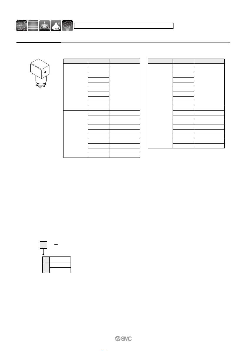
Replacement Parts
VX02 N 12A
2
5
3
6
For VX2
For VX2
For VX2
1
4
1
2
∗ 2 mounting screws are shipped together with the bracket assembly.
∗ On the bottom side of the standard body, there is no female thread for mounting a bracket.
Please select XNB.
∗ Select an appropriate DIN connector suitable for the coil insulation type.
64
VX21/22/23 Series
For Air, Medium Vacuum, Water, Oil and Steam
B