i3070series6_Site_Preparation+11-12.3.pdf.pdf - 第15页
Planning 2 Site Preparation 2-3 Figure 2-1 Recommended layouts for E9903G/E9902G Figure 2-2 Recommended layouts for E9905G E9903G/E9902G E9903G/E9902G with side pod 3 m 3 m 2.7 m tes thea d side pod monitor & keyb oa…
2-2 Site Preparation
2 Planning
The System Plan Drawing
Many things need to be done before the system can be installed. If you make a
system plan drawing, you can use it to plan all aspects of site preparation. A
complete drawing should detail power availability, communications cabling,
compressed air and vacuum lines, and system placement with respect to other
equipment. It can also serve to verify physical access.
Before installing the system, determine whether the operator will stand or sit and
whether the operator will work from the right or left side of the testhead. If you want
the monitor and keyboard to be in front of the testhead, install them on the same
side of the testhead as the operator. However, if you want the monitor and keyboard
to be above the testhead, install them on the opposite side from the operator. It is
important to make this decision correctly.
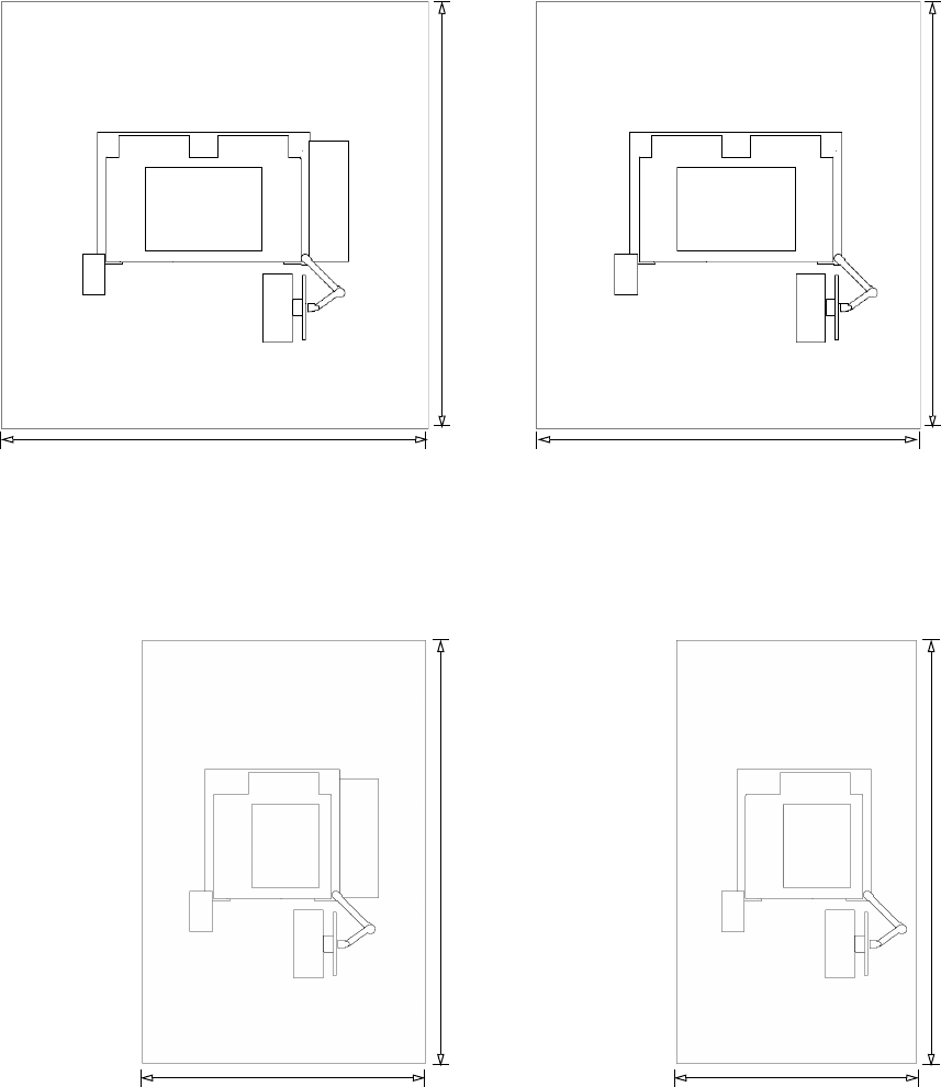
Figure 2-1 and Figure 2-2 show the recommended clearance around the testhead.
See Chapter 3, Structural Requirements for the exact dimensions of individual
testheads.
Always allow 1 meter (3 feet) of space behind the system so service personnel can
access the hardware inside the testhead and operators can access the red PDU
mains disconnect switch.
On your system plan, determine the location of the facility mains disconnect. It
should be installed within 3 meters of the system, where it can be easily reached by
the system operator without requiring the system to be moved to access the
disconnect. See Mains Disconnect on page 6-3 for more information.
Planning 2
Site Preparation 2-3
Figure 2-1 Recommended layouts for E9903G/E9902G
Figure 2-2 Recommended layouts for E9905G
E9903G/E9902GE9903G/E9902G with side pod
3 m
3 m 2.7 m
testhead
side pod
monitor &
keyboard
strip
printer
3 m
E9905GE9905G with side pod
1.7 m
testhead
side pod
monitor &
keyboard
strip
printer
3 m
2 m 1.7 m
3 m
2-4 Site Preparation
2 Planning
Assigning Specialists
The concept of “specialists” represents the recognition that, at most facilities, no
one person will do all the preparatory work.
• Site Coordinator – One person should manage the site preparation process. The
site coordinator will plan the installation, maintain the system plan drawing,
and check off the site prep checklist. The site coordinator may assign all the
other specialists.
• System Administrator – Any successful system requires good system
administration. One person should have responsibility of the system
administration.
• Structural Specialist – The structural specialist will verify that the floor is
suitable for the system in terms of strength and anti-static properties. This
specialist will examine the route from the receiving area to the system’s
proposed location and decide how best to move the system to that place.
Storage will be required after the system is in operation, and the structural
specialist will decide what storage is needed. Chapter 3, Structural
Requirements is the primary reference for the structural specialist.
• EMC Specialist – If the installation is in a location where radiated
radio-frequency (RF) emissions are restricted for this equipment, such as
member states of the European Union, Canada, USA or Australia, an EMC
Specialist is needed to assure that the installation meets the required
attenuation. This specialist will also be responsible to arrange any on-site
testing that may be needed. Chapter 4, RF Attenuation Requirements is the
primary reference for the EMC Specialist.
• Environmental Specialist – The environmental specialist will verify that your
site’s environment is suitable for the system. Air quality, ambient temperature,
cooling capacity, humidity, and electromagnetic interference are areas that the
environmental specialist must address. Chapter 5, Environmental Requirements
contains information for this specialist.
• Electrical Specialist – The electrical specialist will plan and install the mains
power for the system and the convenience outlets for the other system
equipment. These items should be marked on the system plan drawing.
Chapter 6, Power Requirements contains the electrical information.
• Air and Vacuum Specialist – The compressed air and vacuum specialist will
plan and install the compressed air supply for your system. Air lines should be
marked on the system plan drawing. The specialist will also plan and install
your system’s vacuum control system. Vacuum lines should be marked on the
system plan drawing. The information pertaining to air and vacuum control is in
Chapter 7, Compressed Air and Vacuum Requirements.
• Communications Specialist – The communications specialist will install the
LAN cables to your system. LAN cables and telephone lines should be marked
on the system plan drawing.