i3070series6_Site_Preparation+11-12.3.pdf.pdf - 第42页
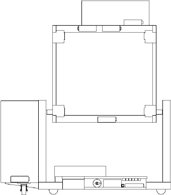
6-10 Site Preparation 6 Power Requirem ents E9905G T est Sy stem Figur e 6-4 shows the locations of the AC outl ets in an E9905G test system with side pod. Figure 6-4 Location of AC outlets in E9905G (r otated, r ear vie…
Power Requirements 6
Site Preparation 6-9
PDU Wiring Diagrams
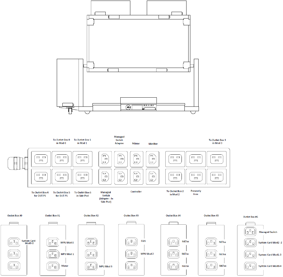
PDU and AC Outlets
E9903G/E9902G Test System
Figure 6-2 shows the locations of the AC outlets in an E9903G/E9902G test system
with side pod.
Figure 6-2 Location of AC outlets in E9903G/E9902G (rotated, rear view)
Figure 6-3 PDU and AC outlets for E9903G/E9902G
Outlet 4
PDU
Outlet 3Outlet 1
Outlet 2Outlet 0
Outlet 6
Outlet 5
Power Requirements 6
Site Preparation 6-11
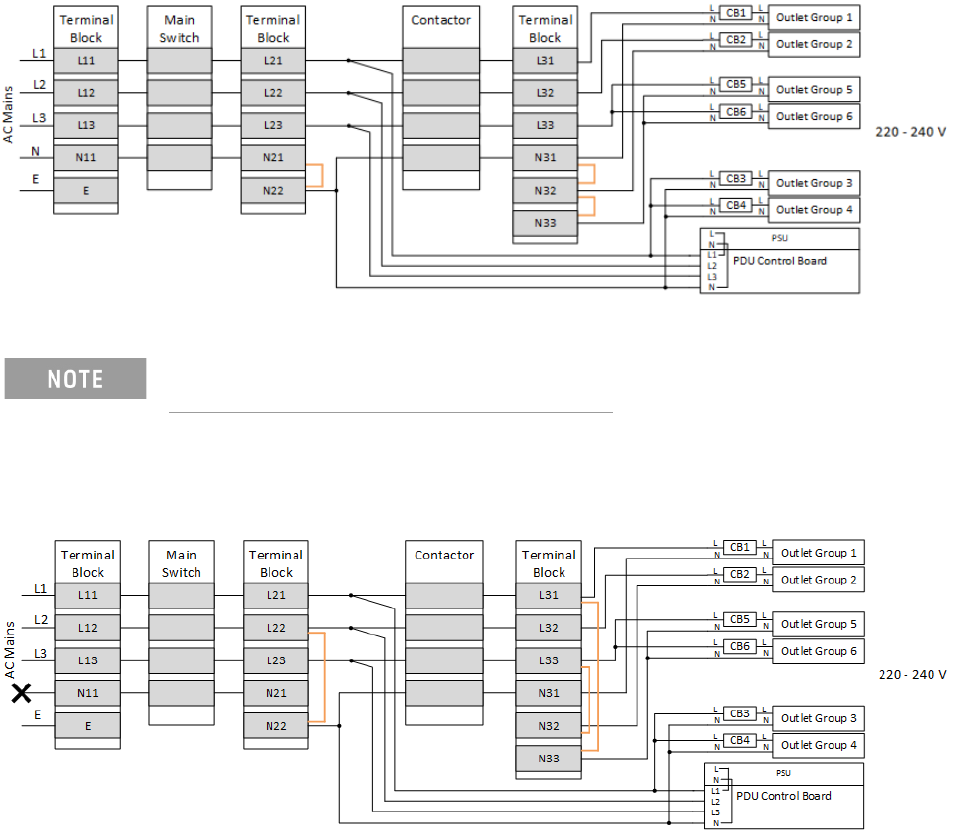
Wiring Diagrams
Note that the PDU phase configuration is determined by the location of the jumper,
as shown by the orange/green lines in the wiring diagrams (the colors do not
indicate the actual colors of the jumper wire).
Figure 6-5 Wiring diagram for 380–415 V input; 3-phase wye with neutral; 220-240 V output
voltage
Figure 6-6 Wiring diagram for 200–240 V; 3-phase wye or 3-phase delta
380-415 V output voltage is not supported.