i3070series6_Site_Preparation+11-12.3.pdf.pdf - 第37页
Power Requirements 6 Site Preparation 6-5 Sizing the Input Wi re s and Circuit Breakers Ta b l e 6 - 1 shows the full-l oad amps (FLA) for each syst em type. Ta b l e 6 - 1 Power r equirements PDU Po we r Option Frequenc…
6-4 Site Preparation
6 Power Requirements
Power Drop
• A dedicated power drop must be provided for the system due to its high current
requirements.
• Copper wire must be used for the power drop.
• An electrician must determine the wire size for the power drop. The wires must
be sized to ensure that the voltage at the system does not drop below
90 percent of nominal (see Calculating the Minimum Voltage below).
Calculating the Minimum Voltage
The voltage at the system must be at least 90 percent of nominal. To calculate the
minimum rms voltage multiply the rms voltage by 0.9. To calculate the minimum
peak voltage, multiply the rms voltage by 0.9 and then 1.414. For example:
208 volts rms * 0.9 * 1.414 = 265 volts peak
Power Requirements 6
Site Preparation 6-5
Sizing the Input Wires and Circuit Breakers
Table 6-1 shows the full-load amps (FLA) for each system type.
Table 6-1 Power requirements
PDU
Power
Option
Frequency Voltage
line-to-neut /
line-to-line
Full-Load Amps (FLA) for:
E9905G E9903G/
E9902G
200–240V 3-Phase Delta 3PD 50/60 Hz 200
220
230
240
18
18
18
18
24
24
24
24
208–220V 3-Phase Wye 3PY 50/60 Hz 208
220
18
18
24
24
380–415V 3-Phase Wye
with Neutral
3PN 50/60 Hz 220 / 380
230 / 400
240 / 415
10
10
10
16
16
16
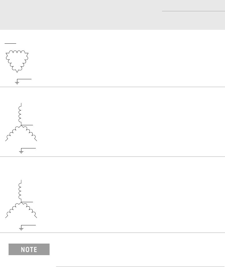
Neutral is not used by the systems for power options 3PD and
3PY. Neutral is shown in the diagrams because Neutral is
cabled into the PDU.
L1
L3
L2
G
N (optional)
L1
L3
L2
G
N (optional)
L1
L3
L2
G
N
6-6 Site Preparation
6 Power Requirements
Basic Power Quality Survey
Power quality can affect system performance differently. The following procedure
is intended as a guideline and may not be the total solution. Failure to meet these
guidelines should serve as an indicator that a power quality consultant might be
needed to conduct a more in-depth power quality survey.
1 With the system operating, measure harmonic distortion at the system-input
connection. THD should be less than 5% and less than 3% for any single
harmonic.
2 With the system operating, measure the ground-to-neutral voltage at the
system-input connection; the voltage should be less than 4vp-p.
3 Turn the system power off and measure the line voltage at the system-input
connection; record this reading. Turn the system on and begin operating mode.
Measure the line voltage at the system-input connection again. The difference
between the two measurements should be less than 2%.
Other problematic power qualities include momentary voltage interruptions,
ground noise, and voltage spikes. A survey of these problems and others may
require the services of a power quality expert with specialized equipment.