i3070series6_Site_Preparation+11-12.3.pdf.pdf - 第38页
6-6 Site Preparation 6 Power Requirem ents Basic Power Quality Survey Power quality can affect system performa nce differ ently. The following pr ocedur e is intended as a guideline and may not be the t otal solution. Fa…
Power Requirements 6
Site Preparation 6-5
Sizing the Input Wires and Circuit Breakers
Table 6-1 shows the full-load amps (FLA) for each system type.
Table 6-1 Power requirements
PDU
Power
Option
Frequency Voltage
line-to-neut /
line-to-line
Full-Load Amps (FLA) for:
E9905G E9903G/
E9902G
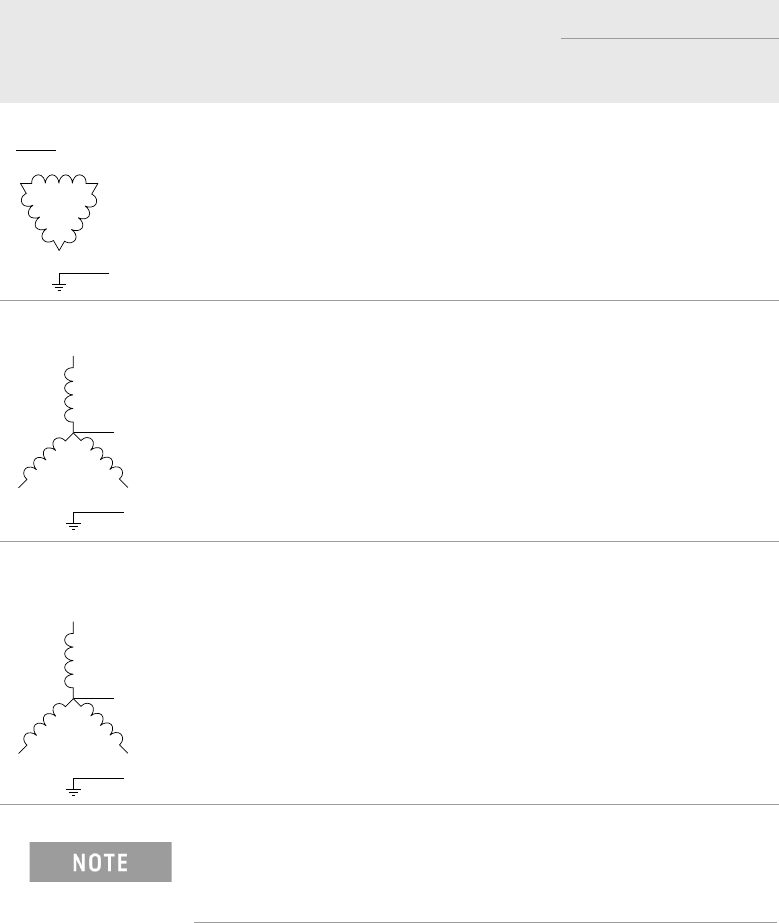
200–240V 3-Phase Delta 3PD 50/60 Hz 200
220
230
240
18
18
18
18
24
24
24
24
208–220V 3-Phase Wye 3PY 50/60 Hz 208
220
18
18
24
24
380–415V 3-Phase Wye
with Neutral
3PN 50/60 Hz 220 / 380
230 / 400
240 / 415
10
10
10
16
16
16
Neutral is not used by the systems for power options 3PD and
3PY. Neutral is shown in the diagrams because Neutral is
cabled into the PDU.
L1
L3
L2
G
N (optional)
L1
L3
L2
G
N (optional)
L1
L3
L2
G
N
6-6 Site Preparation
6 Power Requirements
Basic Power Quality Survey
Power quality can affect system performance differently. The following procedure
is intended as a guideline and may not be the total solution. Failure to meet these
guidelines should serve as an indicator that a power quality consultant might be
needed to conduct a more in-depth power quality survey.
1 With the system operating, measure harmonic distortion at the system-input
connection. THD should be less than 5% and less than 3% for any single
harmonic.
2 With the system operating, measure the ground-to-neutral voltage at the
system-input connection; the voltage should be less than 4vp-p.
3 Turn the system power off and measure the line voltage at the system-input
connection; record this reading. Turn the system on and begin operating mode.
Measure the line voltage at the system-input connection again. The difference
between the two measurements should be less than 2%.
Other problematic power qualities include momentary voltage interruptions,
ground noise, and voltage spikes. A survey of these problems and others may
require the services of a power quality expert with specialized equipment.
Power Requirements 6
Site Preparation 6-7
Connecting Power to the PDU
Connect the system inlet cable to the circuit breaker at the installation site.
3PD/ 3PY
3PN
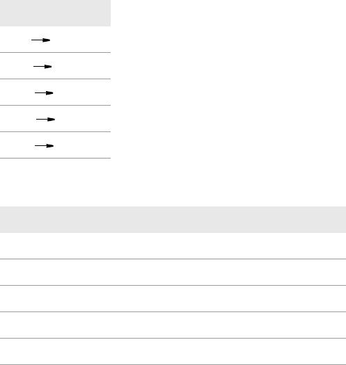
WIRE CHART
BLK X
RED Y
ORG Z
WHT W
GRN G
PLUG TERMINAL ID USE WIRE COLOR
N NEUTRAL BLUE
L1 PHASE 1 BROWN
L2 PHASE 2 GREY
L3 PHASE 3 BLACK
G GROUND GREEN