i3070series6_Site_Preparation+11-12.3.pdf.pdf - 第27页
RF Attenuation Requirements 4 Site Preparation 4-5 Figure 4-1 Determining Available Sit e Attenuation Ta b l e 4 - 2 Determining Available Sit e Attenuation with a site allowance or a differ ent wall attenuation Par a me…
4-4 Site Preparation
4 RF Attenuation Requirements
Calculating Site Attenuation
To obtain the necessary attenuation at the installation site you can increase the
distance between the equipment and the property boundary or you can add walls
or other attenuating structures:
• Required Site Attenuation (R)
R = Target Site Attenuation – Site Allowance
Where:
• Target Site Attenuation = 15 dB
• Site Allowance for your site = ____________
• The distance from the equipment to the property boundary (D) can be
calculated as follows:
D = 30 or 30*log
-1
((R – n * W)/20) whichever is greater.
Where:
• R = Required Site Attenuation
• n = Number of concrete walls between equipment and property boundary.
• W= Attenuation of the wall (a concrete wall without openings has an
attenuation of 10 dB)
• Additional attenuation (X) due to a D greater than 30 meters.
X = 20log(D/30)
Where:
• D = distance from equipment to property boundary.
• Total attenuation (A) is calculated as follows:
A = X + n * W
Where:
• X = Additional Attenuation
• n = Number of concrete walls between equipment and property boundary.
• W= Attenuation of the wall (a concrete wall without openings has an
attenuation of 10 dB)
RF Attenuation Requirements 4
Site Preparation 4-5
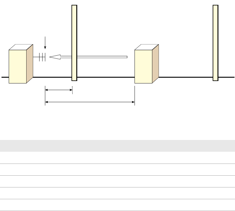
Figure 4-1 Determining Available Site Attenuation
Table 4-2 Determining Available Site Attenuation with a site allowance or a
different wall attenuation
Parameter Value
R; Required Site Attenuation (dB)
n; Number of Walls
W; Attenuation per wall
R – n *W ; Remaining Attenuation Requirement (dB)
D; Distance from Equipment to Real Estate Border (m)
Measuring Point
Wall
Equipment
RF Field
30 m
Distance D
Wall
4-6 Site Preparation
4 RF Attenuation Requirements