i3070series6_Site_Preparation+11-12.3.pdf.pdf - 第35页
Power Requirements 6 Site Preparation 6-3 Power Requirements • Mains Disconnect • Po we r D rop • Basic P ower Quality Survey • Connecting Power t o the PDU Mains Disconnect A mains disconnect — pr oviding over -curre nt…

6-2 Site Preparation
6 Power Requirements
Customer Responsibilities
It is the customer’s responsibility to (a) prepare the site with adequate AC power for
the system, and (b) connect the system to the AC power source. These are not
Keysight’s responsibilities.
Read Power Requirements on page 6-3. In most cases this section will describe all
you need to do to prepare your site.
About the PDU
The PDU (Power Distribution Unit) is the device in the system to which you will
connect AC power.
The PDU is wired differently for different power configurations. The voltage of the
PDU is marked on the front panel of the PDU. If you install a system in a location in
which the actual power does not match the power configuration of the PDU, you
may need to rewire the outlet connections in the PDU (see Is PDU Re-wiring
Necessary? on page 6-8).
After connecting power to the system, do not power up the
system. A Keysight service representative will verify the
power and complete the system installation and verification.
Power Requirements 6
Site Preparation 6-3
Power Requirements
• Mains Disconnect
• Power Drop
• Basic Power Quality Survey
• Connecting Power to the PDU
Mains Disconnect
A mains disconnect — providing over-current and short-circuit protection — must
be provided for the system. The mains disconnect should be in the form of a
multi-pole circuit breaker.
The mains disconnect must:
• Comply with UL 489/CSA C22.2 No.5 standard; rated current 20 A or below.
• Open all line conductors and neutral conductors where local code applies, but
not the protective earth conductor.
• Be marked “System Mains Disconnect” or the equivalent in your local language
• Be marked with a “|” for the “On” position or “O” for the “Off” position.
• Be capable of being locked in the “Off” position, but not in the “On” position.
• Be installed within 3 meters of the system, where it can be easily reached by
the system operator without requiring the system to be moved to access the
disconnect.
• Be rated for a minimum of 10,000 amps interrupting capacity (AIC) if used on a
200–240 volt circuit, or 14,000 AIC if used on a higher voltage circuit.
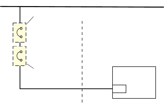
Figure 6-1 Wiring diagram
20 A / 3-Ph breaker
or three 20 A fuses
System
PDU
Installation site
Existing breaker from Series 5 installation
30 A / 3-Ph breaker
or three 30 A fuses
New breaker for Series 6
Keysight
equipment
AC Voltage Source
6-4 Site Preparation
6 Power Requirements
Power Drop
• A dedicated power drop must be provided for the system due to its high current
requirements.
• Copper wire must be used for the power drop.
• An electrician must determine the wire size for the power drop. The wires must
be sized to ensure that the voltage at the system does not drop below
90 percent of nominal (see Calculating the Minimum Voltage below).
Calculating the Minimum Voltage
The voltage at the system must be at least 90 percent of nominal. To calculate the
minimum rms voltage multiply the rms voltage by 0.9. To calculate the minimum
peak voltage, multiply the rms voltage by 0.9 and then 1.414. For example:
208 volts rms * 0.9 * 1.414 = 265 volts peak