5M-1751-004w_G5S.pdf - 第75页
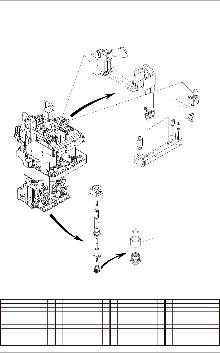
1-23 Pneumatic and Mounting Diagrams 5OM-1751 NOZZLE1 NOZZLE2 7 10 12 Multi-Functional Head Unit (Mounting Diagram) 1305-002 No. Name Q’ty No. Name Q’ty No. Name Q’ty No. Name Q’ty 7 Regulater 1 10 Solenoid V alve Unit 3…
1-22
Pneumatic and Mounting Diagrams
5OM-1751
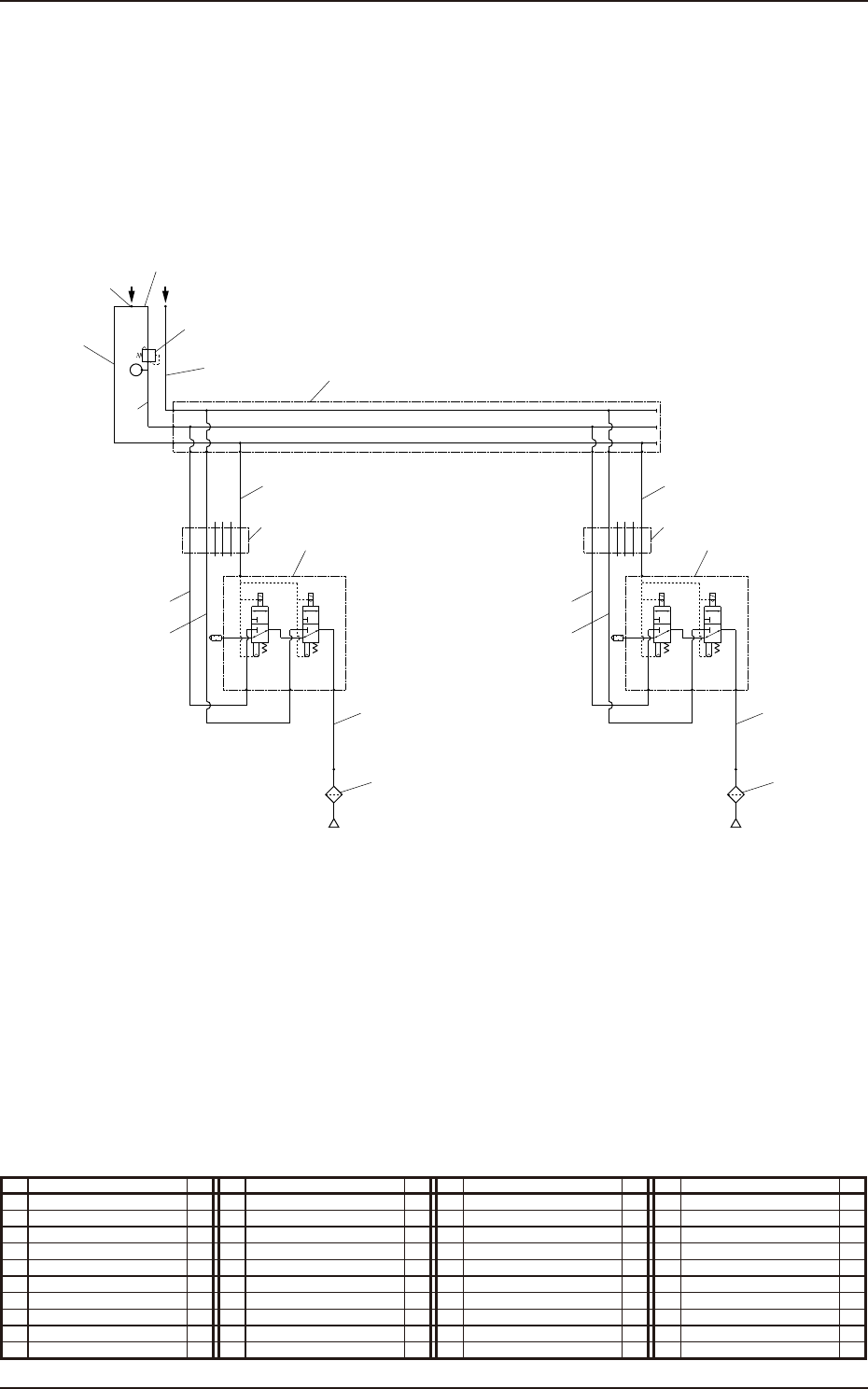
Multi-Functional Head Unit (Pneumatic Diagram)
No. Name Q’ty No. Name Q’ty No. Name Q’ty No. Name Q’ty
1 Tube
φ
6 1 11 Union Y 1
2 Tube
φ
6 1 12 Manifold Unit 3
3 Tube
φ
6 1 13 Solenoid Valve Unit 2
4 Tube
φ
6 1 14 Vacuum Filter 2
5 Tube
φ
6 2 15 Robot Cable 2
6 Tube
φ
6 2
7 Tube
φ
6 2
8 Tube
φ
8 1
9 Tube
φ
4 2
10 Regulater 1
1305-002
2
1
SETUP
0.025MPa
3
Air IN Vacuum
11
10
Nozzle 1
5
6
7
8
9
12
13
14
15
Nozzle 2
5
6
7
9
13
14
15
1-23
Pneumatic and Mounting Diagrams
5OM-1751
NOZZLE1
NOZZLE2
7
10
12
Multi-Functional
Head Unit (Mounting Diagram)
1305-002
No. Name Q’ty No. Name Q’ty No. Name Q’ty No. Name Q’ty
7 Regulater 1
10 Solenoid Valve Unit 3
12 Vacuum Filter 3
1-24
Pneumatic and Mounting Diagrams
5OM-1751
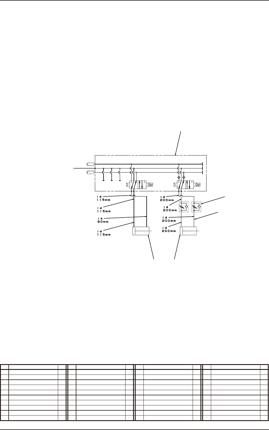
Nozzle Stocker for Multi-Functional Nozzle (Pneumatic Diagram)
No. Name Q’ty No. Name Q’ty No. Name Q’ty No. Name Q’ty
1 Tube
φ
4 1
2 Solenoid Valve 1
3 Speed Controller 2
4 Cylinder 1
5 Cylinder 1
1305-002
4
From the Inside of Whole Base
Stocker 1 U/D Shutter 1 Open/Close
5
2
3
1