Detailed Circuit Diagram Folder SIPLACE F5.pdf - 第16页
SIPLACE F5 Det ailed Circ uit Diagram Folder 01/2001 U S Edition 0 Drawing Number ing System 16 I 0.2 S tructure of the T echni cal Numbering System Document number A docu ment nu mber con sists of an item nu mber , prod…
SIPLACE F5 Detailed Circuit Diagram Folder
01/2001 US Edition
0 Drawing Numbering System 15
I
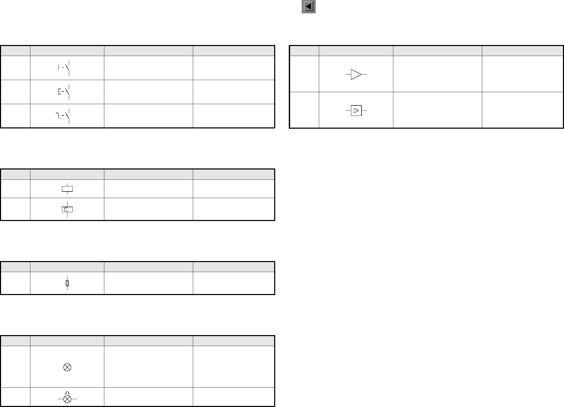
0.1.24 Handbetätigte Schalter / Single-pole switches
0.1.25 Elektromechanische Antriebe / Operating devices
0.1.26 Sicherungen und Sicherungsschalter / Fuses and fuse-switches
0.1.27 Leuchtmelder und Signaleinrichtungen / Lamps and signalling devices
0.1.28 Verstärker / Amplifiers
Nr. / No. Schaltzeichen / Symbol Beschreibung Description
07-07-01 Handbetätigter Schalter, allgemein
Manually operated switch,
general symbol
07-07-02
Druckschalter (nicht rastend)
Taster
Push-button switch (non-locking)
07-07-04 Drehschalter (rastend) Turn-switch (locking)
Nr. / No. Schaltzeichen / Symbol Beschreibung Description
07-15-01
Elektromechanischer Antrieb, allgemein
Relaisspule, allgemein
Operating device, general symbol
07-15-21
Elektromechanischer Antrieb eines
Thermorelais
Actuating device of a thermal relay
Nr. / No. Schaltzeichen / Symbol Beschreibung Description
07-21-01 Sicherung, allgemein Fuse, general symbol
Nr. / No. Schaltzeichen / Symbol Beschreibung Description
08-10-01
Lampe, allgemein
Leuchtmelder, allgemein
RD rot
YE gelb
GN grün
BU blau
WH weiß
Lamp, general symbol
Signal lamp, general symbol
RD = red
YE = yellow
GN = green
BU = blue
WH = white
08-10-02 Leuchtmelder, blinkend Signal lamp, flashing type
Nr. / No. Schaltzeichen / Symbol Beschreibung Description
10-15-01
Verstärker, allgemein
dargestellt mit Ein- und Ausgang
Anmerkung:
Die Spitze des Dreiecks muß in die
Übertragungsrichtung zeigen.
Amplifier, general symbol
Repeater, general symbol
shown with input and output
Note:
The triangle is pointed in the direc-
tion of transmission.
10-15-02
Verstärker, allgemein
dargestellt mit Ein- und Ausgang
Anmerkung:
Die Spitze des Dreiecks muß in die
Übertragungsrichtung zeigen.
Amplifier, general symbol
Repeater, general symbol
shown with input and output
Note:
The triangle is pointed in the direc-
tion of transmission.

SIPLACE F5 Detailed Circuit Diagram Folder
01/2001 US Edition
0 Drawing Numbering System 16
I
0.2 Structure of the Technical Numbering System
Document number
A document number consists of an item number, product status, document status, document type, language and for-
mat.
Item number
An item number consists of master number and function status
Function status (FS) = versions relevant to function
All documents pertaining to an item number have the same functions status. The versions of a product relevant to func-
tion are determined by the totality of the features describing the function and documented in the corresponding docu-
mentation.
Product status (PS)
The versions of a product not relevant to function are determined by the totality of the remaining features (no features
with relevance to function) and documented in the corresponding documentation.
Document status (DS)
The status of the contents of a technical document.
Document type
Language
Format
Document number
Item number
Example 00324139 - 02 01 04 Z D 3
Pattern
NNNNNNNN
-
NN NN NN
AAN
Main number S FS PS DS DT L F
Separator = - for standard part
Separator = S for service part
Function status as per SN 10370, Part 1
Product status as per SN 10370, Part 1
Document status as per SN 10370, Part 1
Document type
Language
Format
N = Numerical counting position
A = Alphabetic counting position
A Installation diagram, electrical B Construction specifications, electrical
E
Adjustment specifications, testing and inspection
instructions, setting specifications
F Movement diagram, general functions drawing
G Machine identification plate K Terminal diagram, cable diagram, wires list
L Circuit Diagram M Assembly diagram, installation diagram, mechanical
N Master pattern, layout, inscription P Program documentation
R Product description S Parts list
T Parts drawing U Documentation overview
V Construction specifications, mechanical W Hydraulics diagram
X Pneumatics diagram Z Assembly, mechanical
D German E English
F French I Italian
N Dutch S Spanish
X German/English Y German/Italian
0A0 1 A1
2A2 3 A3
4A4
1 Detailed Circuit Diagrams 17
I
1 Detailed Circuit Dia
g
rams
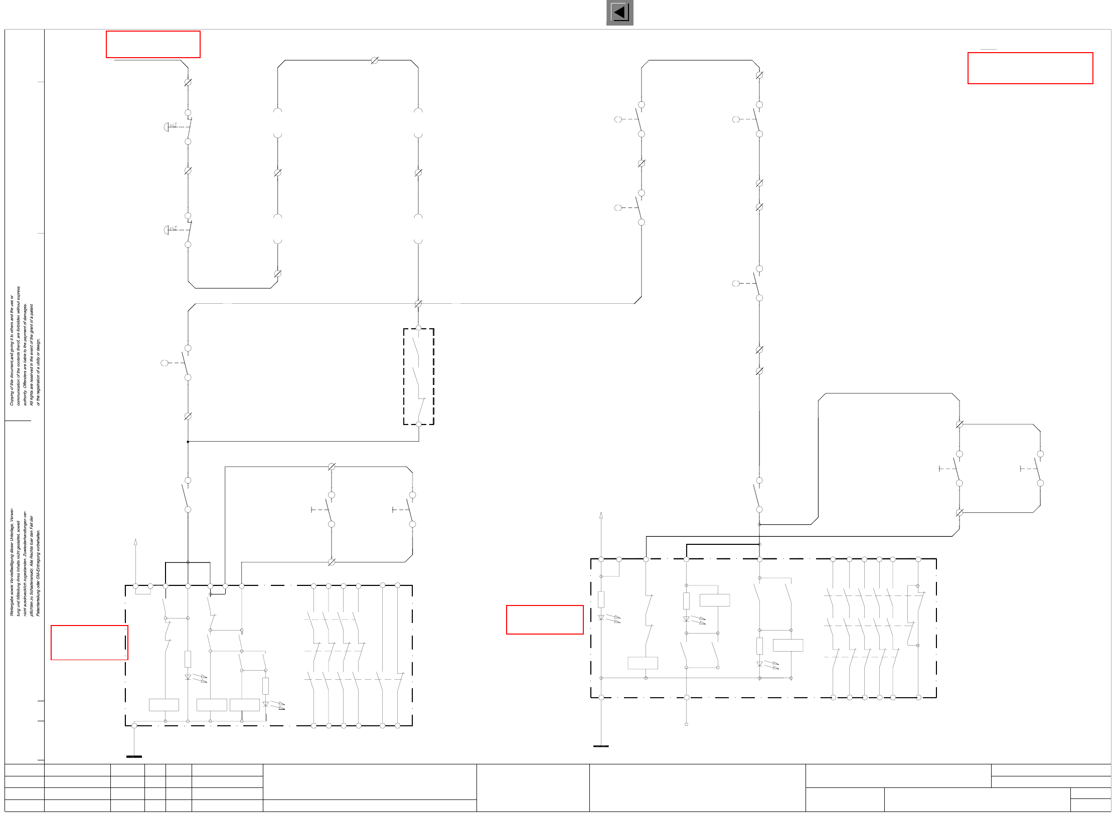
NOT1 EMERG.-STOP circuit, SIPLACE F5
X211 terminal strip (lefthand side)
Note:
00321432-xx pk
00321432-xx gr
00321113-xx ye
00321434-xx pk
00321434-xx gr
00321113-xx gn
input
push-button
output
push-button
C906-S2
4
33
4
X211/16
X211/17
C907-S2
00321113-xx bl
14
13
C0615-W1 ye
Y0615-W1 gn
X211/14
X211/13
22
21
X211/12
Output conveyor
Y0438-S1
switch
Protective cover
X211/10
21
22
X211/11
X211/9
21
22
21
22
00305815-xx ye
00305815-xx gn
00321573-xx gn
00321573-xx ye
00321574-xx gn
00321574-xx ye
C0435-S1
Input conveyor
switch
Protective cover
Protective cover
switch
switch
Protective cover
Y0414-S1
lefthand side
righthand side
00322070-xx lbl
00322070-xx br
00322069-xx br
Component table, righthand side
Component table, lefthand side
00321436-xx br
00321436-xx wh
00321433-xx br
00321433-xx wh
00321086-xx 24VAC
00321113-xx wh & br
push-button
push-button
Y0907-S1
Y0906-S1
X211/4
2
1
X211/3
2
1
X211/2
Y0413-S1
X211/6
1a 00322063-xx/X37
2c 00322063-xx/X37
1a 00322064-xx/X37
2c 00322064-xx/X37
00321113-xx bk
00321434-xx brgn
00321434-xx whye
00321113-xx vio
4
3
X211/15
switch
Key-operated
00321113-xx rdbl
00321432-xx ye
00321432-xx gn
4
3
4
3
00321434-xx ye
00321434-xx gn
00321113-xx grpk
X211/19
X211/18
44
43
C0952-K3
C906-S2
On
input
C907-S2
output
On
NOT1.DWG
Stromlaufplan/Circuit diagram
PL EA
Hi
18.12.2000
SIEMENS
SMD Placement System SIPLACE F5
1
2
EMERG.-STOP circuit
SIPLACE F5
H2’: LED ready
L2
H1’: LED release
H1’
3414
65
conveyor conveyor
OnOn
OPTION: Cover switch, succeeding machine
Connect cable 00305817-xx to X211/13 gn - X211/14 ye
Warning: If you install the option
remove jumper X211/13 - X211/14.
remove jumper X211/11 - X211/12.
Warning: If you install the option
Connect cable 00305816-xx to X211/11 gn - X211/12 ye
OPTION: Cover switch, preceding machine
00344266-xx
Push-buttonPush-button
conveyor conveyor
for machine ’ON’
software release signal
Monitoring
for machine ’ON’
software release signal
Monitoring
C0952-K3
54
53
C0952-K1
Y0907-S4
X211/8
X211/7
To power supply
Output conveyor
Input conveyor
unit
Safety protection
C0952-K2
Safety protection
C0952-K1
unit
EMERG.-STOP
EMERG.-STOP
24
44
58
K2’
K1’
K1’
K3’
H2’
K2’
L1
K1’
X1 X2 X3
24V AC
K3’
K2’
K3’
K1’ K3’
K1’
K2’K1’
X5
K3’
X4 X6
33
13
23 43 57
66
65
H3: LED channel 1
H2+H3 = releasePOWER SUPPLY
H1: LED MAIN
UNIT
L2
X6
H2: LED channel 2
14
54
34
24
44
66
K1’
K2’
H1
L1
K3’
X1 X4
K3’K1’
H3
H2
K1
X3
K3’
K1’
24V AC
K2’K2’
K1’
K2’
K2’
X5
K3’
13 53
3323
43
00322069-xx lbl
X211/5
00322111-xx ye
00322111-xx gn
4c 00322104-xx/X57
3c 00322104-xx/X57
WPC interface, lefthand side
WPC interface, righthand side
3c 00322105-xx/X57
4c 00322105-xx/X57
00322112-xx ye
00322112-xx gn
Status Modified Date Name Stand.
Check.
Author
Date
Mat. no.:
CAD file:
Orig./Creat. f./Creat.by
Sh.
Sh.
See page 57
See page 58
See page 58
See page 86