Detailed Circuit Diagram Folder SIPLACE F5.pdf - 第18页
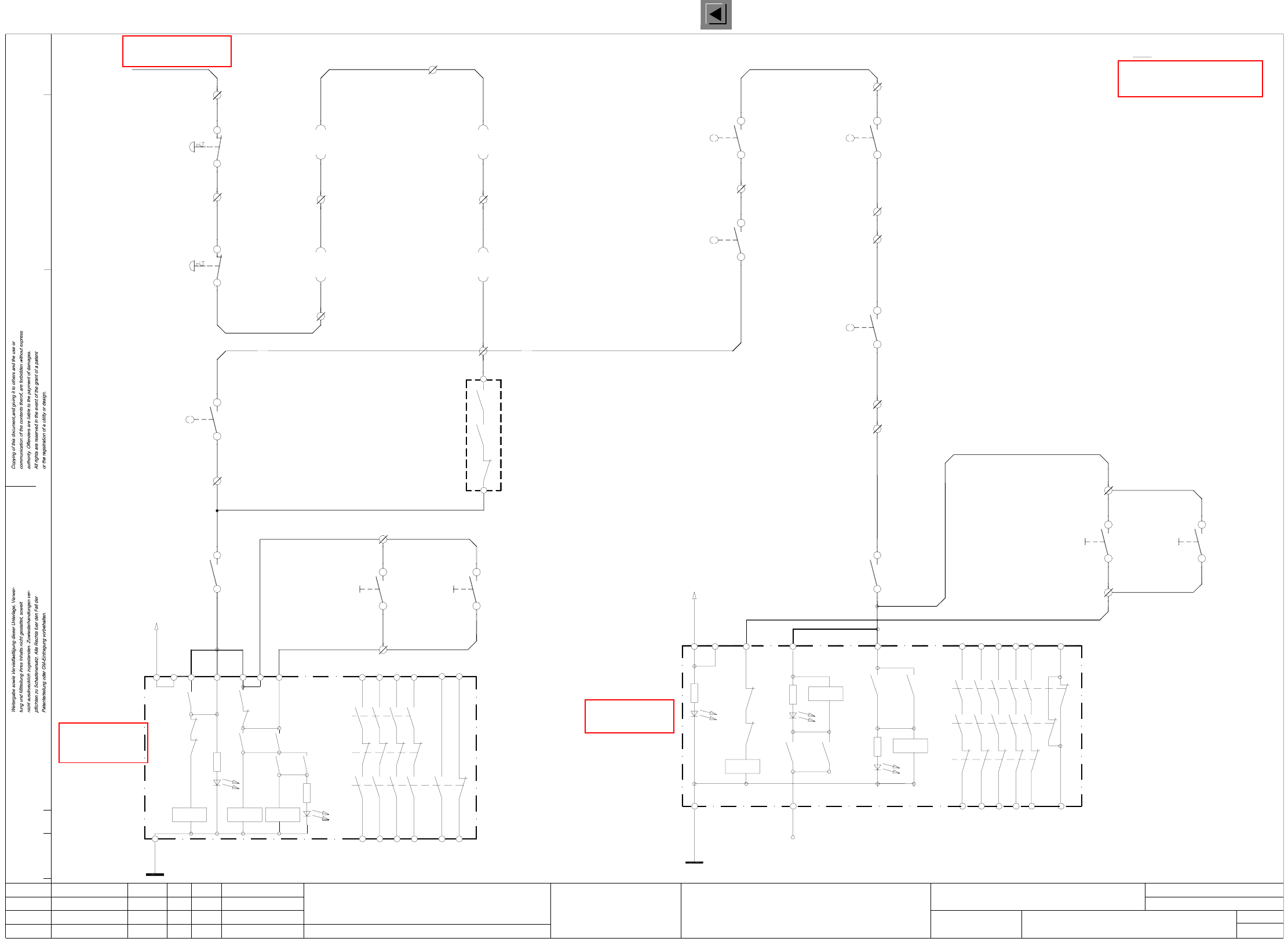
1 Detailed Circuit Diagr ams 18 I NOT2 EMERG .-STOP circuit - signa ling circuit, SIPLACE F 5 Y0906-S2 Y0907-S1 Y0906-S1 On butto n EMERG . STOP 00321433-xx ye 0032143 6-xx ye 00321433- xx grpk 00321433- xx rd 00321436- …
1 Detailed Circuit Diagrams 17
I
1 Detailed Circuit Dia
g
rams
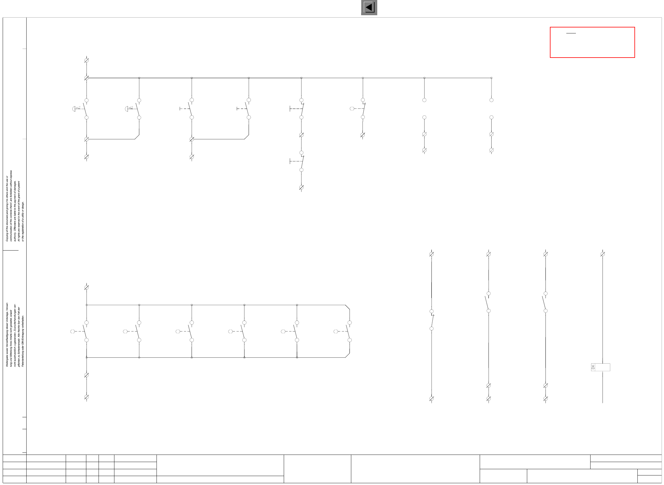
NOT1 EMERG.-STOP circuit, SIPLACE F5
X211 terminal strip (lefthand side)
Note:
00321432-xx pk
00321432-xx gr
00321113-xx ye
00321434-xx pk
00321434-xx gr
00321113-xx gn
input
push-button
output
push-button
C906-S2
4
33
4
X211/16
X211/17
C907-S2
00321113-xx bl
14
13
C0615-W1 ye
Y0615-W1 gn
X211/14
X211/13
22
21
X211/12
Output conveyor
Y0438-S1
switch
Protective cover
X211/10
21
22
X211/11
X211/9
21
22
21
22
00305815-xx ye
00305815-xx gn
00321573-xx gn
00321573-xx ye
00321574-xx gn
00321574-xx ye
C0435-S1
Input conveyor
switch
Protective cover
Protective cover
switch
switch
Protective cover
Y0414-S1
lefthand side
righthand side
00322070-xx lbl
00322070-xx br
00322069-xx br
Component table, righthand side
Component table, lefthand side
00321436-xx br
00321436-xx wh
00321433-xx br
00321433-xx wh
00321086-xx 24VAC
00321113-xx wh & br
push-button
push-button
Y0907-S1
Y0906-S1
X211/4
2
1
X211/3
2
1
X211/2
Y0413-S1
X211/6
1a 00322063-xx/X37
2c 00322063-xx/X37
1a 00322064-xx/X37
2c 00322064-xx/X37
00321113-xx bk
00321434-xx brgn
00321434-xx whye
00321113-xx vio
4
3
X211/15
switch
Key-operated
00321113-xx rdbl
00321432-xx ye
00321432-xx gn
4
3
4
3
00321434-xx ye
00321434-xx gn
00321113-xx grpk
X211/19
X211/18
44
43
C0952-K3
C906-S2
On
input
C907-S2
output
On
NOT1.DWG
Stromlaufplan/Circuit diagram
PL EA
Hi
18.12.2000
SIEMENS
SMD Placement System SIPLACE F5
1
2
EMERG.-STOP circuit
SIPLACE F5
H2’: LED ready
L2
H1’: LED release
H1’
3414
65
conveyor conveyor
OnOn
OPTION: Cover switch, succeeding machine
Connect cable 00305817-xx to X211/13 gn - X211/14 ye
Warning: If you install the option
remove jumper X211/13 - X211/14.
remove jumper X211/11 - X211/12.
Warning: If you install the option
Connect cable 00305816-xx to X211/11 gn - X211/12 ye
OPTION: Cover switch, preceding machine
00344266-xx
Push-buttonPush-button
conveyor conveyor
for machine ’ON’
software release signal
Monitoring
for machine ’ON’
software release signal
Monitoring
C0952-K3
54
53
C0952-K1
Y0907-S4
X211/8
X211/7
To power supply
Output conveyor
Input conveyor
unit
Safety protection
C0952-K2
Safety protection
C0952-K1
unit
EMERG.-STOP
EMERG.-STOP
24
44
58
K2’
K1’
K1’
K3’
H2’
K2’
L1
K1’
X1 X2 X3
24V AC
K3’
K2’
K3’
K1’ K3’
K1’
K2’K1’
X5
K3’
X4 X6
33
13
23 43 57
66
65
H3: LED channel 1
H2+H3 = releasePOWER SUPPLY
H1: LED MAIN
UNIT
L2
X6
H2: LED channel 2
14
54
34
24
44
66
K1’
K2’
H1
L1
K3’
X1 X4
K3’K1’
H3
H2
K1
X3
K3’
K1’
24V AC
K2’K2’
K1’
K2’
K2’
X5
K3’
13 53
3323
43
00322069-xx lbl
X211/5
00322111-xx ye
00322111-xx gn
4c 00322104-xx/X57
3c 00322104-xx/X57
WPC interface, lefthand side
WPC interface, righthand side
3c 00322105-xx/X57
4c 00322105-xx/X57
00322112-xx ye
00322112-xx gn
Status Modified Date Name Stand.
Check.
Author
Date
Mat. no.:
CAD file:
Orig./Creat. f./Creat.by
Sh.
Sh.
See page 57
See page 58
See page 58
See page 86
1 Detailed Circuit Diagrams 18
I
NOT2 EMERG.-STOP circuit - signaling circuit, SIPLACE F5
Y0906-S2Y0907-S1Y0906-S1
On buttonEMERG. STOP
00321433-xx ye 00321436-xx ye 00321433-xx grpk
00321433-xx rd00321436-xx gn00321433-xx gn
ONON
output conveyorinput conveyoroutput conveyor
push-button
input conveyor
push-button
X2KD+ (+24V)
X210/3
00321416-S1
00321417-S1 00303614-S1
14
1313
1414
13
00305818-xx wh
00305818-xx br
Cover protective
switch
output conveyor
C0614-W1 br
00305817-xx wh
13
1400321421-S1
13
14
C0952-K3
A2
A1
C0952-K1 C0952-K1
43
44
X211/21
X2KD/8 (S5 input)X2KD/1 (S5 input)
X211/22
58
57
+ 24V+ 24V
X2KB/7 (S5 input)
C0952-K3
22
21
+ 24V
X2KC/8 (S5 output)X212/4X212/4X212/4
K1
00321113-xx grbr00321113-xx whgn00321113-xx whye00321113-xx whye
00321113-xx brgn00321113-xx yebr00321113-xx whgr
Software release
Monitoring K2
Control On
to GND
Control On
Monitoring K3
Software release
X212 terminal strip (lefthand side)
X211 terminal strip (lefthand side)
X210 terminal strip (lefthand side)
Note:
13
14
Cover protective
lefthand side
switch
Cover protective
00321573-xx br
switch
righthand side
00321573-xx wh 00321574-xx wh
00321574-xx br
Cover protective
input conveyor
switch
preceding
switch
Cover protective
00305815-xx br
00305815-xx wh 00305816-xx wh
00305816-xx br
Cover protective
switch
succeeding
NOT2.DWG
Stromlaufplan/Circuit diagram
PL EA
Hi
18.12.2000
SIEMENS
SMD Placement System SIPLACE F5
2
2
EMERG.-STOP circuit - signaling circuit
SIPLACE F5
00344266-xx
Signaling circuit Signaling circuit Signaling circuit Signaling circuit
S5 output
X2KC/M
blbk blbk
monitoring of control ON and software release signal
Signaling circuits
Cover switch signaling circuit
EMERG.-STOP signaling circuits, ON/OFF push-buttons, key-operated switches
blbk
Cover open
X2KD/3 (S5 input)
machine
(Option)
00321617-S1 00321421-S1
(Option)
machine
Push-button Push-button Push-button
blbk
Off button
00321432-xx vi
00321433-xx bk
Key-operated switch
00321434-xx bk00321432-xx vi00321432-xx grpk
00321434-xx rd00321432-xx rd00321432-xx rd
input conveyor
OFF
output conveyor
OFF
X2KD/6X210/5
X2KD/5
C0906-S3
Y0907-S3
X210/4
X2KD/4X2KD/2
X210/2
X210/1
X2KD + (+24V)
Y0907-S2
4
3
4
3
4
3
4
3
2
11
2
blbk blbk
(S5 input) (S5 input)
1
2
(S5 input)
Key-operated
switch
Y0907-S4
Push-button
(S5 input)
EMERG.-STOP EMERG.-STOP
(S5 input)
EMERG. STOP
X210/2
X2KD/2
blbk
00322111-xx pk
00322111-xx gr
6c 00321104-xx/X57
5c 00321104-xx/X57
WPC interface, lefthand side WPC interface, righthand side
6c 00321105-xx/X57
5c 00321105-xx/X57
00322112-xx pk
00322112-xx gr
EMERG. STOP
(S5 input)
blbk
X2KD/2
X210/2
Status Modified Date Name Stand.
Check.
Author
Date
Orig./Creat. f./Creat.by
CAD file:
Mat. no.:
Sh.
Sh.
See page 86
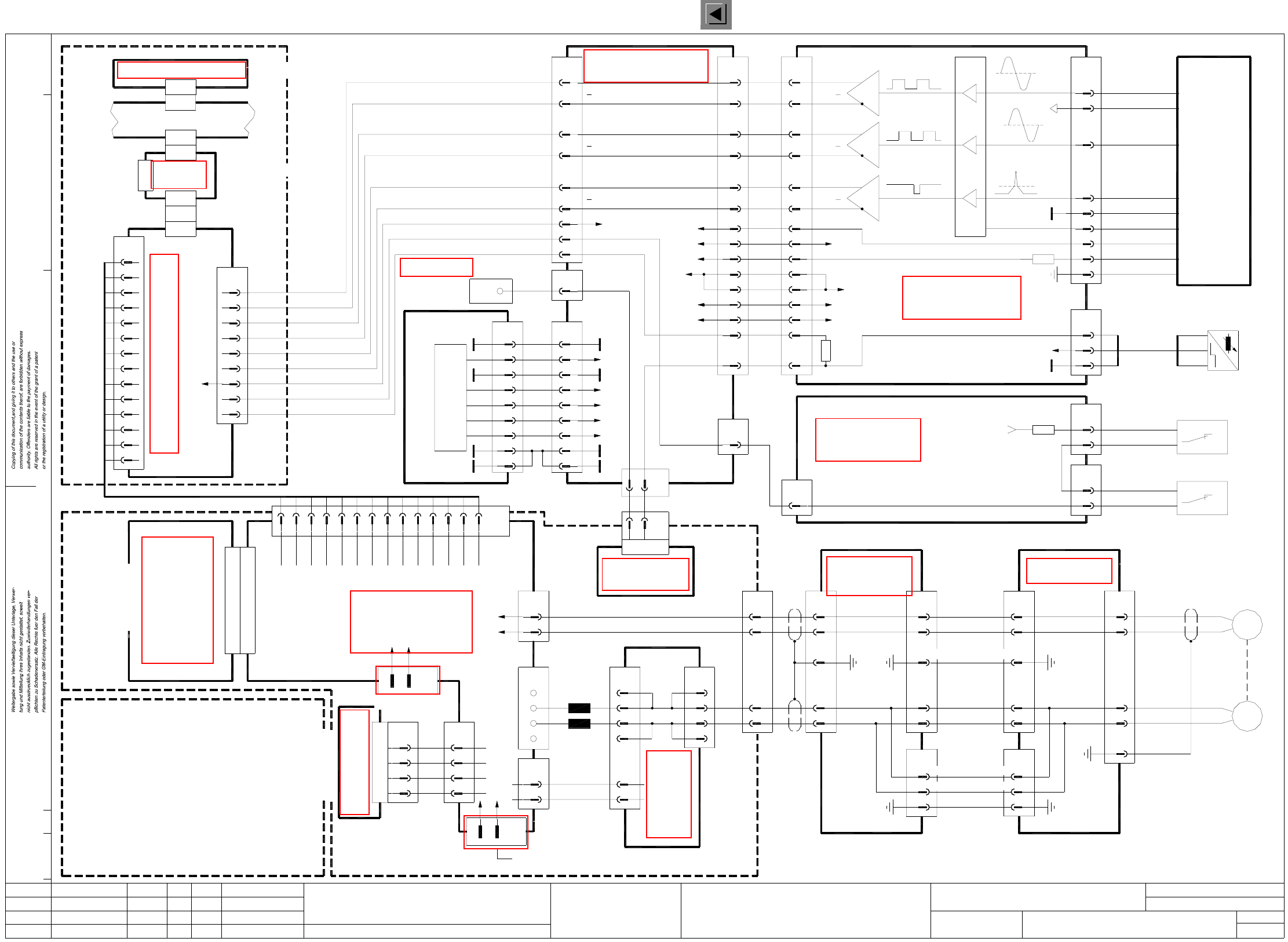
1 Detailed Circuit Diagrams 19
I
X1 X-axis, gantry 1, SIPLACE F5
X1.DWG
Stromlaufplan/Circuit diagram
PL EA
Hi
18.12.2000
SIEMENS
SMD Placement System SIPLACE F5
1
1
X axis
SIPLACE F5
GND
Track B
3
4
2
1
Track A
X-axis incremental shaft encoder
X15ac
6
9
8
7
5
gnwh
bk
rd
bl
wh
br
ye
pk
gn
Zero pulse
Signal
(Track N)
screen
LED
GND
+5V
LED
00300911-xx
(Cable)
8
9
27
26 Track N
Track N27
26
X3ac
00322258-xx
6
5
2
3
29
30
33
32
X3aa
(Cable)
Track B
Track B29
30
Track A
Track A
33
32
X15aa
10
12
13
GND
A
A
B
B
N
N
13
11 Analog GND
Servo unit
backplane
V nom9
GND Servo10
Tacho-std or f/V12
screen
Force13
14
X2va
00321538-xx
(Cable)
X11su
X1sz
7
8
5
6
00321036-xx
3
4
1
2
8
9
5
6
2
3
X5su
X1sm
A6 (sm)
SMP bus A32 (su)
Axis board
X22
X7sz
X2sm
X3sm
X axis,
axis tracks
X1sa
GND
X5va
3
1
T+
T-
X7va
1
2
5
6
M+
M-
X4va
1
4
X7va
3
4
0/100V
-
X3va
33
4
00344266-xx
Terminal strip
X2kf
1
(cable)
00321587-xx
wh
(lefthand side)
gantry 1
Crash signal
00322262-xx
(cable)
00302849-xx
signal
anti-crash board)
13,2813,28
+5V
+5V
11
12
11
12
X10aa
24
X2ab
24
bl3 bl -
X16ac
1
2
(Cable)
00300609-xx
br
bk bk
br
+
A1
End pos. prox.
switch B1
+24V
00321190-xx
Gantry
X8ab
3
1
wh
br
(Cable)
00321577-xx
Limit switch 1
x axis
00321423-xx
End pos. bero
B1, B2
y axis
00321425-xx
Limit switch 2
x axis
00321578-xx
(Cable)
X9ab
3
1
wh
br
Conversion board
00321189-xx (ab)
large axis
S1 S2
conversion board
X36aa
5
3
4
2
1
(cable)
(aa)
X11aa
23
24
3,5,7,9
2,4,6,8
00322264-xx
524
2,4,6,8
3,5,7,9
M-
M+
1
2
00321189-xx
conversion board
23
(cable)
X1ab
(ab)
large axis
4
X3ab
T+
T-
M+
M-
1,10,11,12,13,14,15,16,17,18,19,34
00321420-xx (W2)
(cable)
bl
br
bk
br
X10aa
2,4,6,8,10,12,14,16,18
3,5,7,9,11,13,15,17,19
X2ab
00322262-xx
(cable)
1,20,341,20,34
3gegr
9
8
7
6
5
+5V
-15V
+15V
+5V
+24V
X18
2
3
4
X12aa
1
+5V
00321190-xx (aa)
Gantry conversion board
End pos. bero
Reference point
End pos. bero 1
X-axis rel. sign.
T+
T-
Servo unit
00334638-xx
X1
00322100-xx A10
X11e
1
X1
Anti-crash board
A10 00322100-xx
00321547-xx
(cable)
66
X35aa
2
4
1
2
2
1
T+
T-
EN
+15V
yebk
yebk
yebk
yebk
X11a
Anti-crash board
8b GND (dyn. brake)
Dyn. brake control6d
from anti-crash board
from anti-crash board
14b
14z
X7
pkbk
pkbk
wh
18d
26d
24z
16z
10d
8zbrpk
Dynamic brake
x axis
A8
Brake
MT
L2
L1
X7
M+
M-
20z
22d
4z
6d
X5
1
3
br
pk
M+
M-
5
6
T+
T- br
vi
(W2)
+15V
+5V
U/2
2525
2222
-15V
-15V
+15V
16
31
16
31
T
T
10
19
GND
+24V
10
19
GND
+24V
00330647-xx (ac)
X34aa
1
Control unit
Power supply
00341851-xx
00344771-xx
+24V
00321439-xx
(cable)
+5V
+15V
-15V
00321420-xx (W1)
(cable)
br
wh
br
wh
bk
00321537-xx
(W1)
00321537-xx
(cable)
-15V
+15V
1
2
X6va
00320855-xx
head board, digital
SP6-12
8
9
2
4
5
7
6
3
1
bl
br
ye
gr
rd
pk
gn
wh
Status Modified Date Name Stand.
Check.
Author
Date
Mat. no.:
CAD file:
Orig./Creat. f./Creat.by
Sh.
Sh.
X2sz
Machine controller M44 A1 (sa)
X1 plug assignment / servo amplifier
Servo ready
Analog GND
Sensor stop
Force
nom
12z
12d
10d
V
8d
8z
Tacho (-)
- 15 V
GND Servo
Tacho (+)
+ 15 V
4d
4z
6z
2z
2d
M+
M+
Power (+Vb)
Power (+Vb)
Power (0V)
Power (0V)
24z,b,d
22z,b,d
30z,b,d
32z,b,d
28z,b,d
26z,b,d
Servo Enable
M-
M-
I²t
Ia monitor
18z,b,d
20z,b,d
16d
14d
16z
A1
00321732-xx
TDS 120 / 12,5 X
X1
X-axis servo amplifier
X1va
screen1
00341851-xx
Control unit
Cable 00321890-xx
rd
nom. values
X axis
109
Axis rear panel, A27 (sz)
Servo Enable (ENV from
x axis
8 screen
Servo Enable 3
2
Servo ready4
Sensor control stop
A13 (va)
5I²t
6
Ia monitor7
14
12
13
10
11
12
See page 65
See page 88
See page 108
See page 129
See page 107
See page 76
See page 29
See page 108
See page 28
See page 75
See page 82
See page 65
See page 107
See page 75
See page 106
See page 75