Detailed Circuit Diagram Folder SIPLACE F5.pdf - 第82页
2 Circuit Diagr ams 82 I 0033464 7-010 101 TD3 F5 servo unit, ba sic modu le (v iewed fr om the ba ck) (S h. 3 of 3) 10 21 10 51 0 1 9 3 2 51 56 63 68 Fan unit X3 X2 X4 X80 A14 A13 Y-ax is X-ax is Y-axis X-axis X14 Y mo …
2 Circuit Diagrams 81
I
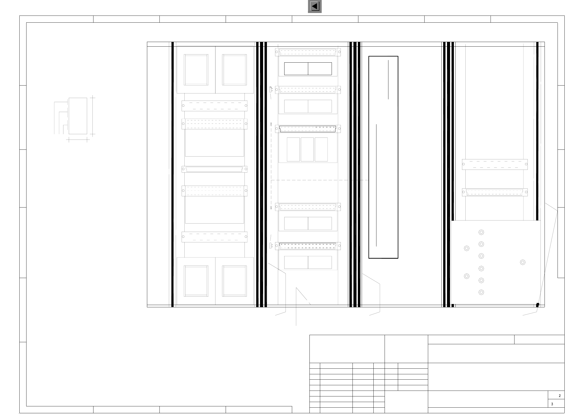
00334647-010101TD3 F5 servo unit, basic module (viewed from the front) (Sh. 2 of 3)
Part 006Part 005
Servo unit 80F4 / 6 base
17.06.1997
Tekin
00334647-01
334647T1
1.
16.09.97
1.
Tek
1.
16.09.97
16.09.97
Tek
Tek
00334647-010101TD3
2L+/5L+2L+
7L+
2L+/5L+
DP1-axis, SP head, "A15"
Dynamic brake, X
X-axis, "A13"
Y-axis, "A14"
Anti-crash board X11
Dynamic brake, Y
X7
X8
Ballast circuit
Z-axis, IC head, "A19"
DR-axis, IC head, "A18"
Stern SP head, "A17"
Z-axis, SP head, "A16"
A: Identification label, assembly inscription according to recommendation VA-F-510-001
(flush with the front plate):
Apply the following labels inside
* Note
B: Inspection label, identification: testing eng., year, month
Manufacturer/location of plant according to SN 37040
Date (year/month/day) according to SN 01007
Numeral
Prepare the labeling tapes A-C
acc. to material no. 323329
and fit them.
Inscription
tape C
* Note
Inscription
tape B
Inscription
tape A
"A20"
Sheet
Sh.
CAD-Datei:
Mat-Nr.:
Status Modified Date Name
Stand.
Check.
Author
Date
Scale
Contact springs are inserted in parts 005 and 006 of the guide rails.
The contact springs are to be inserted only on the front side and only in the
bottom rail of the SP-head and IC-head Z servos.
Note !
SMD-Placement System Siplace 80F4
Product status
Doc. status
Function status
6-nozzle revolver head
Power supply unit
X12
X13
1:2
(viewed from the front)
007
GND
6L+ 24V 12V 5V
009008
005005004003002001
L2
L1
L4
L3
Fan unit
18
40
00334647 / 01
AA-BBBB-CCCC
SIEMENS AUT 5
Siemens AG
1
1
243
2345678
A
B
C
D
E
F
A
B
C
D
AUT5-BSM
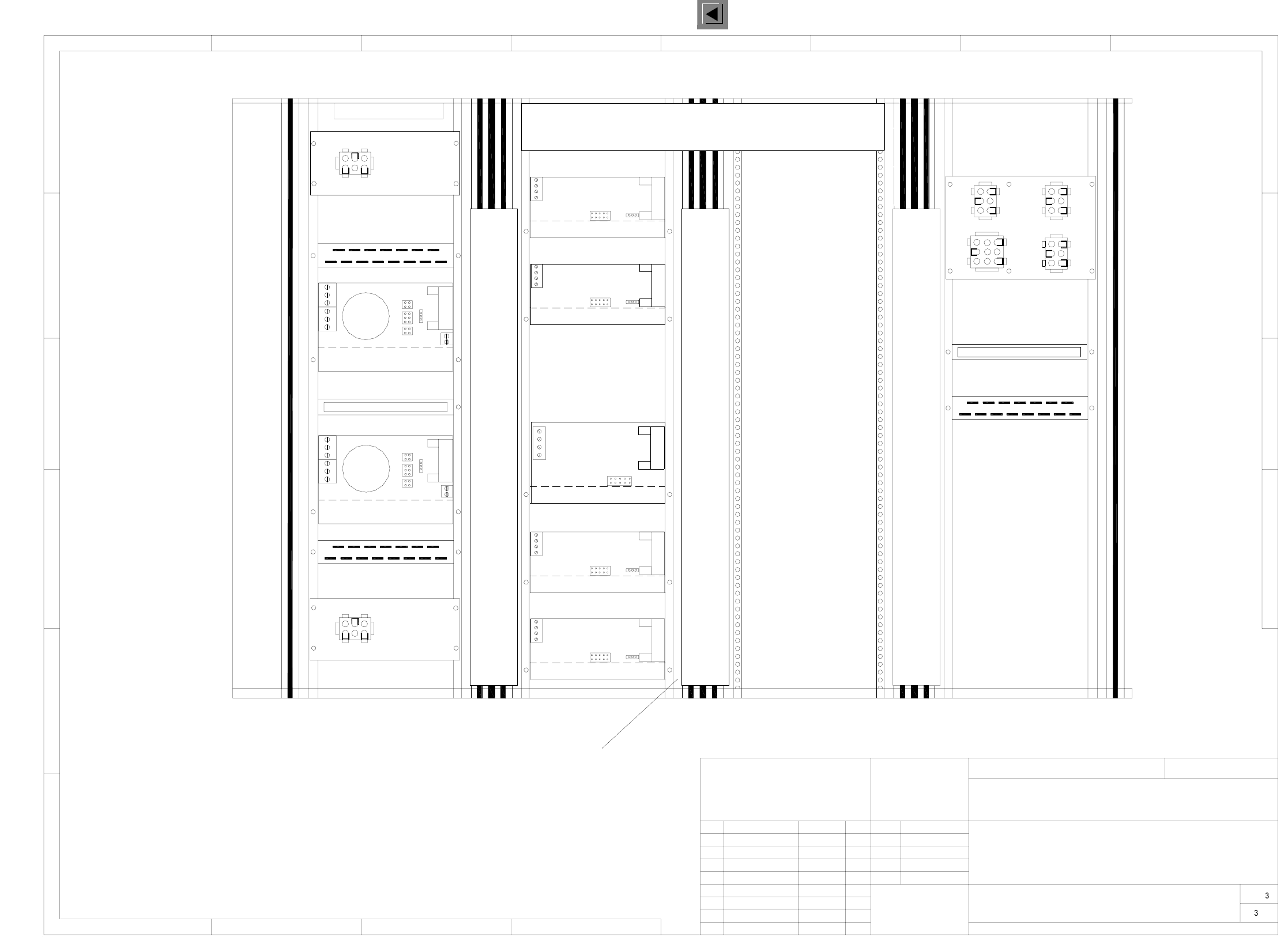
2 Circuit Diagrams 82
I
00334647-010101TD3 F5 servo unit, basic module (viewed from the back) (Sh. 3 of 3)
10 21
10
510 19 32
51 56 63 68
Fan unit
X3X2
X4
X80
A14
A13
Y-axis
X-axis
Y-axis
X-axis
X14
Y motor
X6
X motor
X5
Ballast circuit
Power supply unit
Dynamic brake, Y
Dynamic brake, X
Anti-crash board
Siemens AG
1
1
243
2345678
A
B
C
D
E
F
A
B
C
D
AUT5-BSM
A16
X4
Z-axis
X2
X1 (vd)
X3
X4
X3
A17
X2
X1 (vc)
A18
X4
DR-axis
X2
X1 (vg)
X3
A19
X4
Z-axis
X2
X1 (vk)
X3
1:2
(viewed from the back)
16 27 49 60 71
38
X11
X7
X1 (va)
X5X4
X6
X2
X7
X1 (vb)
X6
X5X4
X2
1-84 (2mm)
Numerical tape
60x30 l=300mm
60x30 l=300mm
Cable duct 003
Cable duct 002
60x30 l=300mmCable duct 001
30x30 l=250mm
Cable duct 004
38
X12
X13
29
X7
X8
SMD-Placement System Siplace 80F4
Product status
Doc. status
Function status
6-nozzle revolver head
"A20"
Sheet
Sh.
Mat-Nr.:
CAD-Datei:
Status Modified Date Name
Stand.
Check.
Author
Date
Scale
Servo unit 80F4 / 6 base
17.06.1997
Tekin
00334647-01
334647T1
1.
16.09.97
1.
Tek
1.
16.09.97
16.09.97
Tek
Tek
00334647-010101TD3
X3 X3
IC head
IC head
SP head
SP head
SP head
Star
A15
X4
DP1-axis
X2
X1 (vf)
X3
2 Circuit Diagrams 83
I
00321510-070201LD3 Circuit diagram, terminal panel, right-hand side
456 78
17
2L+
9
X206:L1
3456
X206:L2
(rd) (re)
X2
X1
1
(K1)
34 56
123 456 7
1mm²
N
X2
X2
PEPEPEPE
X1
12
NN
56
L2 L3L1
3
L1 4L3 L3L2L2 6
1413 15 16
2L+
1L+ 11
12
1L+ 2
2L+ 3
10mm²
1mm²
89
(rc)
6
4
X206
X207
1
5
C0530
2
Y636-
Y636-
C0530
C938
5L+
PE PE
1L+
1L+
1L+
1L+
(rb)
PEPENN 5
(+24V)
L1
2L+/5L+
2L+/5L+
2L-
1L-
1L+ 4
1L+ 1
7
10mm²
C510-W1
6
3
3
2
6mm²
6mm²
C709
C708
X31
*938/X16
2L+
2L-
2
9
8
D
7
C
A
6
D620-W1
10
8
3
5
56
1mm²
F
342
2
B
A
1
1
1
8
4L+
18 8 8
1mm²
5
10 19 11
1
4
72345
12
X1
12398711
4
76
3
C
D
E
00344540
E
F
00344539
4
1mm²
7
X1
PEN5PEN4
-xx-xx
C511-W1
10 10
6
6L+ 9
7L+ 10
2L+/5L+
3
1
2L-
5
2
1mm²
2L-
C560
6
1
7
3
21
6
L3 PE
*904/X211,X212
K504-W1
(K2)
*935/X3
Y510-W1
*935/X2
C509-W1
2L- 8
D619-W1
(K1)3L+ 5
X206:PE
X206:N
X206:L3
X206:L2
X206:L1
X206:PE
X206:N
X206:L3
18
89
A2
A3 A4 A5
34
L1 L2
R1
21
PL EA1 E
Function status
Product status
Document status
SMD Placement System SIPLACE 80S20/F4
Sheet
Sh.
Status Modified Date Name Stand.
Check.
Author
Date
Orig. Creat. f. Creat. by
Terminal panel, righthand side
Terminal panel
To
Servo unit
To
Servo unit
To
Tape cutter 1
To To
Tape cutter 2
To
Servo
Star point 007
wh
bl&bk
bl&bk
bl&bk
0.5mm²
6L+ unswitched
+7L switched
+7L switched
6L+ unswitched
4.7 Ohm / 5W
bk
bk
1.0mm²
1.5mm²
To
To
WPC interface
righth. side D911
lefth. side, D910
WPC interface
Power supply
To
Power supply
VI rectifier
To
in SIPLACE 80F4 machines only
WPC interface:
ToToTo
Control unit Interface Interface
lefth. side, C955 righth. side C956
To
Power supply
Power supply
SC
To
Option:
From UPSTo UPS
br
br
gn
gn
wh
wh
bk bk
wh
gr
bk
1.5mm²bk
br
gn
ye
gr
pk
bl
wh
Spare
bl&bk
bl&bk
bl&bk
gn
bk bk
wh
wh
gn
gn
wh
wh
wh
gn
ye
gr
wh
br
br
gr
ye
wh
pk
gr
bk
gn&ye
gn&ye
bk
gn&ye
gn&ye To servo unit
To control unit
To cable
To cable
br
bl
gn&ye
br
bl
gn&ye
wh
pk
bk
wh
wh
bl
br
gn&ye
bl
bkbk
bl
bl
bl
rd
br
gr
wh
br
br
br
gn&ye
gn&ye
gn&ye
gn&ye
gn&ye
bl
br
gr
gn&ye
rd
wh
br
wh
wh
gn&ye
br
bl
gn&ye
gn&ye
bl
bk
br
bk
gn&ye
bk
bk
br
bk
bl
When using
a UPS, connect
the cables and
remove jumper
X206:4-5 !
=
SIEMENS AG
+
00321510-070201LD3#
Tuth
21.10.98
08.06.98
01.06.00
21.10.98
01
02
07
Leh
Tu.
Leh
C523-W100300161-06Y511-W1 C516 C517
C506-W1
*952
1
X1
11
4
1
2
(K1)
2
12V
4
6
2L-
1mm²
1mm²
1mm²
C935
5
7L+ 10
6L+ 9
PE
2
(K2)
5
2
1L-
B
2
(K2)
(+24V)
4
1
1
456
123