Detailed Circuit Diagram Folder SIPLACE F5.pdf - 第30页
1 Detailed Circuit Diagr ams 30 I LP01 PCB con veyor 1 + 2, po wer supp ly LP1. DW G Str omlau fpla n/C irc uit diagram PL EA Hi 18.12. 2000 SIEMENS Sh. Sh. SMD Placemen t System SIPLACE F5 1 1 PCB con veyor 1 + 2 Power …
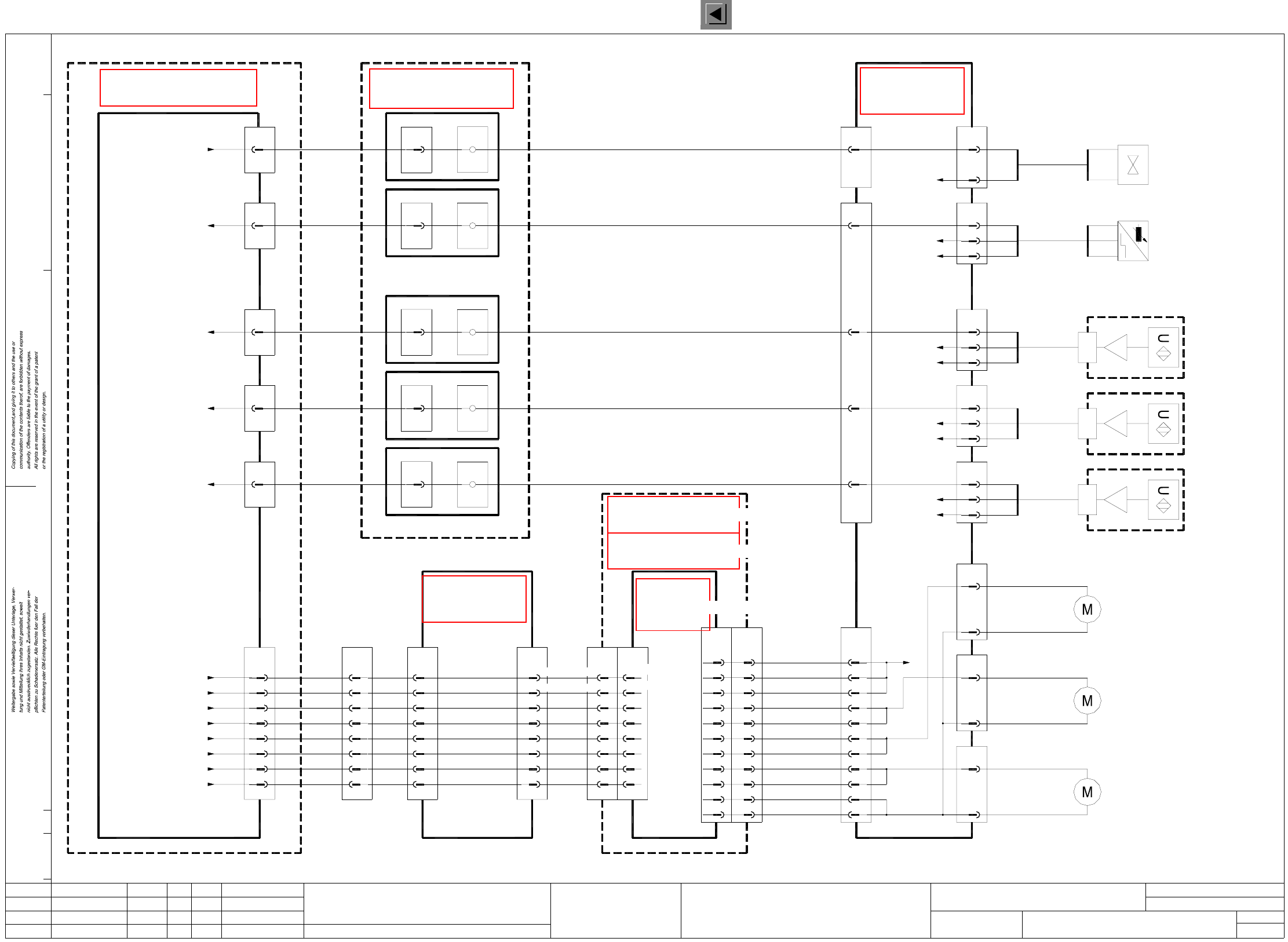
1 Detailed Circuit Diagrams 29
I
SERV2 Power supply for servo amplifier, anti-crash board, SIPLACE F5
SERV2.DWG
Stromlaufplan/Circuit diagram
PL EA
Hi
18.12.2000
SIEMENS
SMD Placement System SIPLACE F5
2
2
Servo amplifier power supply
SIPLACE F5
Backplane A19, Z-axis, Pick&Place-head
X4vk
pkbk
pkgr
-15V
+15V1
2
Backplane A18, DR-axis, Pick&Place-head
18
X12
4
26
12
+/-15V A12
Power supply
16
30
X12
32
30V unswitched
Starpoint 007
1L-, GND
GND
+30V
00343723-xx
righthand side
To terminal strip
X207:19
00322100-xx
A10
Anti-crash board
+24V2
5
4
3
-15V
+5V
GND
1
X11g
+15V
blbk
pkgr
grbk
wh
pkbk
To pin 4 of power supply unit A18
To pin 18 of power supply unit A18
To star point 007
To star point 006
To star point 004
Status Modified Date Name Stand.
Check.
Author
Date
CAD file:
Mat. no.:
Orig./Creat. f./Creat.by
Sh.
Sh.
X4vg
pkbk
pkgr
-15V
+15V1
2
Backplane A16, Z-axis, Collect&Place-head
X4vd
pkbk
pkgr
-15V
+15V1
2
Backplane A15, DP1-axis, Collect&Place-head
X4vf
pkbk
pkgr
-15V
+15V1
2
Backplane A17, DR-axis, Collect&Place-head
X4vc
pkbk
pkgr
-15V
+15V1
2
Backplane A14, Y-axis
X6vb
pkbk
pkgr
-15V
+15V2
1
Backplane A13, X-axis
X6va
pkbk
pkgr
-15V
+15V2
1
X3
5,6
2
Starpoint 002, 6L+
Potential distribution
board
00300398-xx
Servo unit
22
8
See page 79
See page 83
See page 104
See page 77
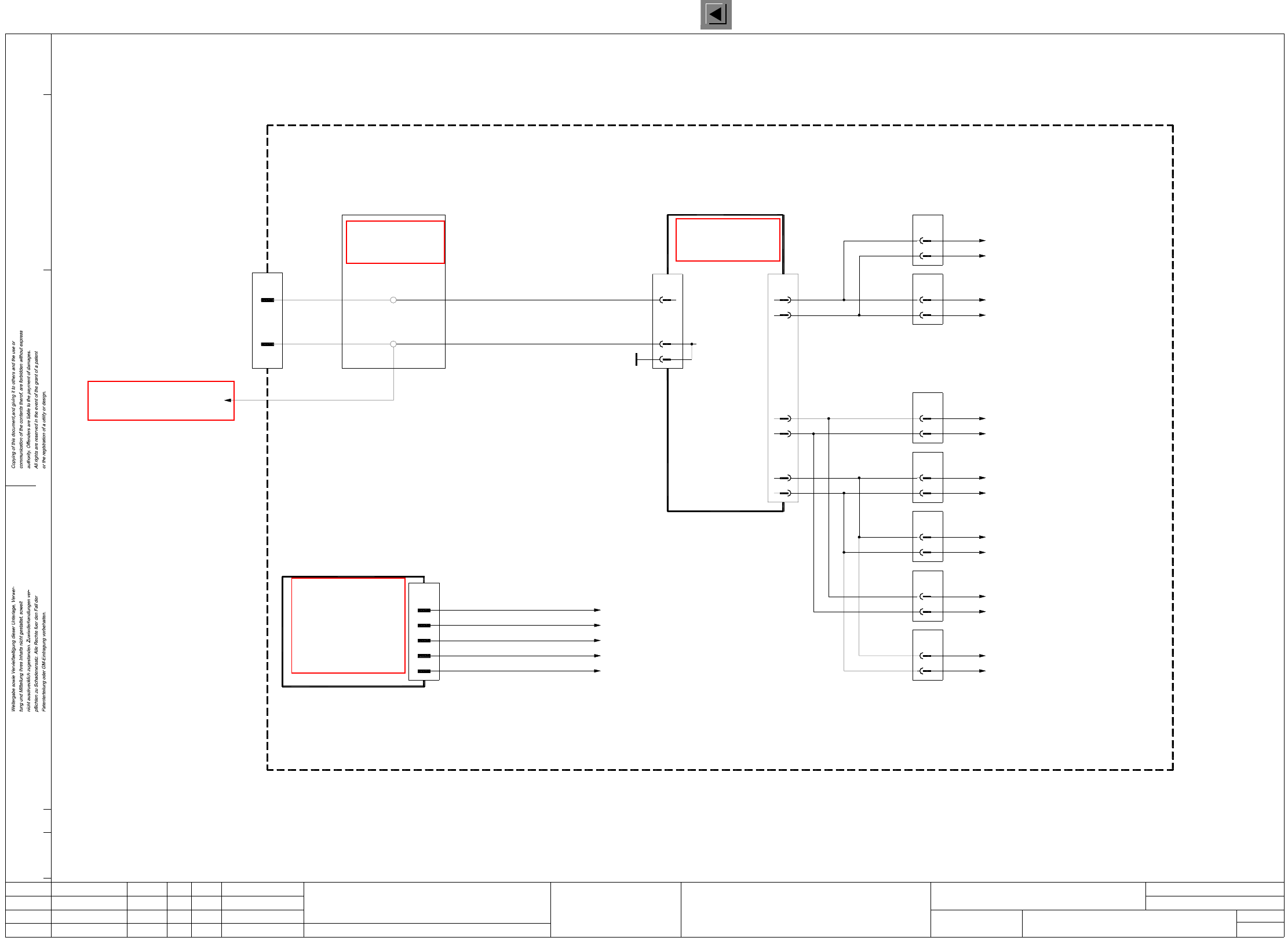
1 Detailed Circuit Diagrams 30
I
LP01 PCB conveyor 1 + 2, power supply
LP1.DWG
Stromlaufplan/Circuit diagram
PL EA
Hi
18.12.2000
SIEMENS
Sh.
Sh.
SMD Placement System SIPLACE F5
1
1
PCB conveyor 1 + 2
Power supply
7
4
6
5
3
2
1
+24VDC
30V switched
30V unswitched
70V switched
+5VDC
+24VDC
GND
00325581-xx
Conversion board
’dual conveyor’
6
GND
7
5
4
3
2
X14
1
bl
gr
pk
br
wh
ye
8
9
gn
+15VDC
GND
GND
+30VDC switched
+5VDC
+24VDC
+70VDC switched
+30VDC unswitched
00334638-xx
Servo unit
(Cable)
00326070-xx 00326063-xx
(Cable)
6-channel
Half-bridge board
00325460-xx
Backplane, lifting table, width adjustment
Fan unit E1
PCB conveyor 2 (Option) 00325580-xx
Backplane, lifting table, width adjustment
PCB conveyor 1 00325580-xx
Control unit - single conveyor 00331465-xx
Control unit - dual conveyor 00327615-xx
or
+5V
5
Not used
Key
Not used
Not used
4
3
2
1
6
7
8
GND
30V switched
Key
X2
X5c
wh
pk
gn
wh
br
gn
ye
gr
pk
bl
4
1
2
3
gn
ye
br
gr
X5a
2
5
4
3
1
Spare
70V switched
30V switched
30V unswitched
GND
wh
br
ye
pk
gn
2
5
4
3
X5b
GND
30V unswitched
30V switched
70V switched
Spare
1
X5d
gr
bl
3
2
1
4
5
6
7
gn
br
wh
ye
gr
pk
bl
X1
M
X2a
X2b
X1c
28a/c
22a/c
32a/c
26a/c
32a/c
22a/c
28a/c
26a/c
24a/c,
24a/c,
24a
24b
23a
23b
22a
22b
21a
21b
J1
X25/27/29/31/33/35/37/39/
41/43/45/47/49/51/53/55/57
(Conveyor 2)
GND
Status Modified Date Name Stand.
Check.
Author
Date
Mat. no.:
CAD file:
Orig./Creat. f./Creat.by
See page 92
See page 80
See page 121
See page 120
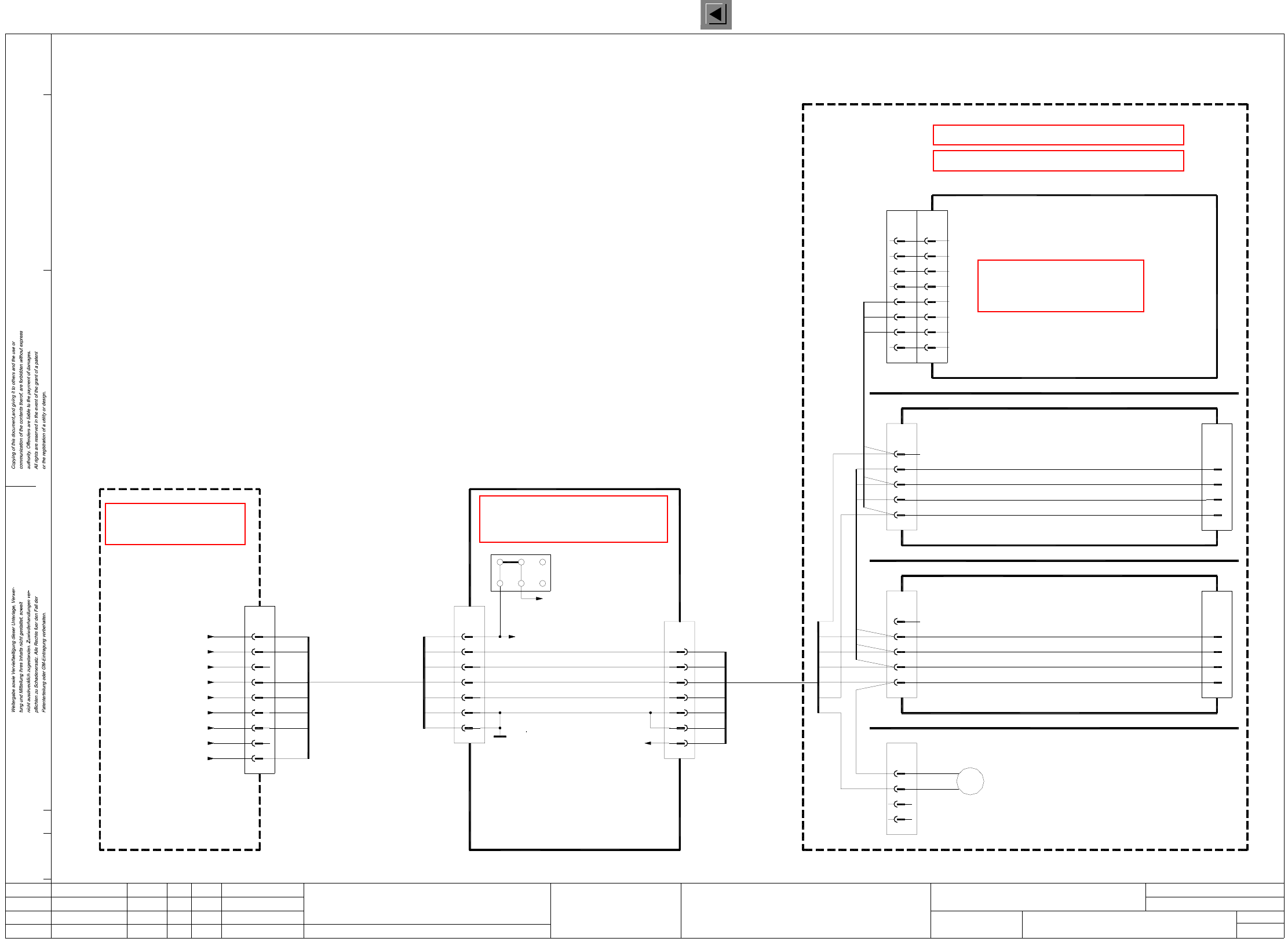
1 Detailed Circuit Diagrams 31
I
LP02 PCB conveyor 1, conveyor motors control
LP2.DWG
Stromlaufplan/Circuit diagram
PL EA
Hi
18.12.2000
SIEMENS
Sh.
Sh.
SMD Placement System SIPLACE F5
1
1
PCB conveyor 1
Conveyor motors control
X20
2
-wh
+br
6
X22
2
output conveyor 1
00326030-xx
Conveyor motor,
Conveyor motor,
center conveyor 1
00326031-xx
Conveyor motor,
input conveyor 1
00326032-xx
GND
+24VDC
br
bk
bl
GND
6
+24VDC
X36
3
2
br
bk
bl
GND
6
+24VDC
X38
3
2
br
bk
bl
GND
6
+24VDC
X40
3
2
bk
bl
GND
6
X42
2
(Cable)
00327655-xx
X34a
Sonar switch,
00326022-xx
input conveyor 1
00327656-xx
(Cable)
center conveyor 1
Sonar switch,
00326023-xx
X36a
00327657-xx
(Cable)
output conveyor 1
Sonar switch,
00326024-xx
X38a
br
bl -
+
bk A1
stopper 1
00326025-xx
Sensor switch,
11
10
7
8
13,14
1,2,3,4
12
1,2,3,4
13,14
9
8
7
12
11
10
Port A3.4
Port A3.5
Port A3.6
Port A3.7
I/O boards
Port A1.6
Port E1.5
Port E4.6
Port E3.6
Port E4.4
00344266-xx
Terminal panel, left-hand side
Valve ’Extend stopper 1’
Sensor switch ’Stopper 1 retracted’
Sonar switch ’output conveyor 1’
Sonar switch ’center conveyor 1’
Sonar switch ’input conveyor 1’
14
15
16
10
11
12
13
9
X7
19
20
7 X1:4
GND
Output conveyor 1
29a
30b
32b
32a
30a
Input conveyor 1
GND
8
9
10
5
6
7
X2c
board
00325460-xx
X3
13,14
1,2,3,4
X1c
+30VDC switched
Center conveyor 1
X3’
29b
27a
28a
28b
27b
26b
X2sf
Port A3.2
GND
+30VDC switched
Port A3.3
00341851-xx
Control unit
(Cable)
00329283-xx
00326067-xx
(Cable)
6
2
X18
-wh
+br
br
bk
bl
6
3
X34
2
-wh
+br
6
10
12
11
9
8
7
8
10
9
7
6
5
13,14,23,24
1,2,3,4,16,17,18
X6
+30VDC switched
GND
Center conv. 1 ’slow’
Center conv. 1 ’fast’
Output conv. 1 ’slow’
Output conv. 1 ’fast’
Input conv. 1 ’slow’
Input conv. 1 ’fast’
dual conveyor
00325581-xx
Conversion board
halfbridge
6-channel
(Cable)
00331297-xx00321501-xx
(Cable)
X1c
5a
4b
5b
4a
3a
3b
1a/b,2a/b,8a,9a/b
7b/a,12b/a
X4c
1
3
4
5
6
7
8
9
10
13
14
00327615-xx
dual conveyor
Control unit -
Control unit -
single conveyor
00331465-xx
Status Modified Date Name Stand.
Check.
Author
Date
Mat. no.:
CAD file:
Orig./Creat. f./Creat.by
+br
-wh
Valve,
00326026-xx
stopper 1
pk
6
X13
(Cable)
00326068-xx
pk
6
X12
12
8
10
rd-bl
rd
vio
Conversion board
’dual conveyor’
00325581-xx
7
X2ka
11
X2se
11
X1ka
00321497-xx
(Cable)
A1
A1
(Cable)
00321499-xx
10
X4se
10
X1kb
7
X2kb
00326069-xx
(Cable)
A4
(Cable)
00321504-xx
11
X5sf
11
X2kg
7
X6kg
00326069-xx
(Cable)
A3
(Cable)
00321503-xx
11
X4sf
11
X1kf
7
X2kf
00326069-xx
(Cable)
A4
(Cable)
00321504-xx
9
X5sf
9
X2kg
5
X6kg
00326069-xx
(Cable)
9
See page 86
See page 121
See page 92
See page 120
See page 121
See page 65
See page 91