Detailed Circuit Diagram Folder SIPLACE F5.pdf - 第51页
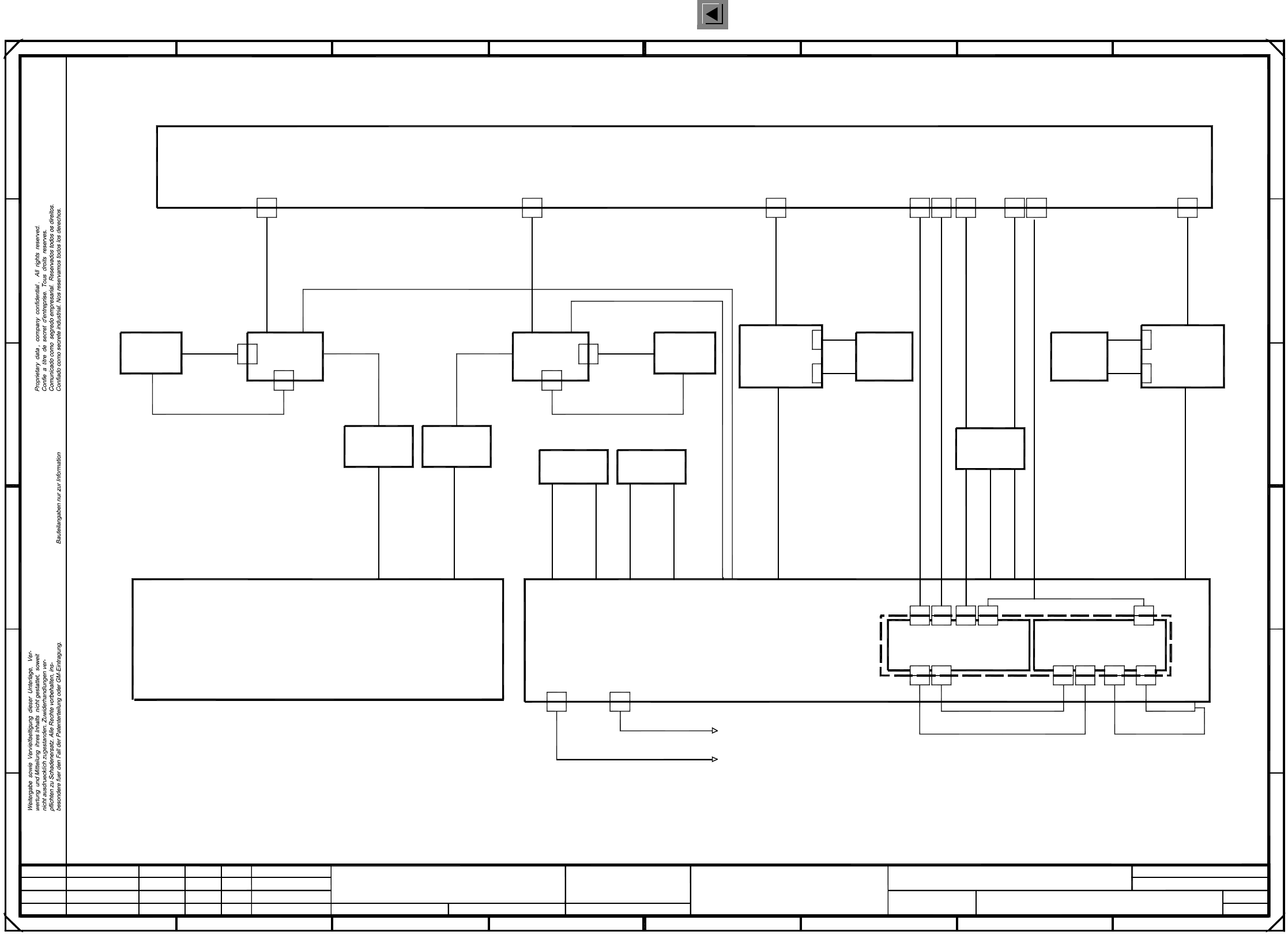
2 Circuit Diagr ams 51 I 001 17251-0 10101LD 3 SIPLACE F5 b asic mod ule (S h. 4 of 4) Creat. by Cre at. f. Orig. Status Stand. Dat e Modified Name Author Check. Dat e = SIEMENS AG + 23 4 567 8 1 E F F E D C B A 00321778…
2 Circuit Diagrams 50
I
00117251-010101LD3 SIPLACE F5 basic module (Sh. 3 of 4)
=
SIEMENS AG
+
Stand.Status DateModified Name Orig. Creat. f. Creat. by
Author
Check.
Date
D
C
B
A
C
D
A
1
765432
B
2345678
1
E
F F
E
X1kk
X1kk
X2kk
X2kk
X4kk
X4kk
X5kk
X5kk
Illumination control
00305883-xx
Illumination control
00305883-xx
00321741-xx
Power supply, output, port 6
00321740-xx
Power supply, output, port 5
00321778-xx
00321779-xx
CO vision module
00306223-xx
00306068-xx
00322277 (W1)-xx
Flash mode
00322365-xx
00306067-xx
00322277 (W3)-xx
00322277 (W2)-xx
00321510-xx
F5 control unit
00341851
8
00322104-xx
for
WP changer
Signal
00322111-xx
X4sd
X4sd
00322107-xx V24
X2sg
X2sg
X3sg
X3sg
X7sc
X7sc
X5sa
X5sa
X21
X21
X1kh
X1kh
X3kh
X3kh
X6kh
X6kh
X5kh
X5kh
X2kh
X2kh
X4kh
X4kh
X3kk
X3kk
00322071-xx
Control signals
00322072-xx
Control signals
00322070-xx
00322069-xx
00321428-xx V24
00321429-xx V24
Interface
righth. side
00322105-xx
Siplace WPC
00302826-xx
X56b
Power
X57b
Signal
for
WP changer
Signal
00322112-xx
X2sd
X2sd
00322108-xx V24
Siplace WPC
00302826-xx
Rating
Signal
X56bX57b
Interface
lefth. side
X3kg
To
station
Communications signals
succeeding
To
station
Interface
righth. side
00322064-xx
Component table
righth. side
00301251-xx
X36b
X36b
Rating
00300380-xx
Signal
Component table
lefth. side
00301251-xx
Interface
lefth. side
00322063-xx
X36a
X36a
00300379-xx
Power
X37a
X37a
00306380-xx
Signal
00341698-xx
Tape cutter
00341698-xx
Operator panel 1
"Input conveyor"
00303636-xx
Communications signals
X3sd
X3sd
X5sd
X5sd
00303636-xx
preceding
Control signals
00321432-xx
Emerg.-stop loop
00321433-xx
Operator panel 2
"Output conveyor"
Control signals
00321434-xx
Emerg.-stop loop
00321436-xx
X37b
X37b
00300379-xx
00321528-xx 00321529-xx
X4kg
X4kg
X3kg
01.
01.
01.
Tek
Tek
Tek
3
4
Terminal panel, lefthand side
Terminal panel, righthand side
00321479-xx
Control
00313400-xx
Control
00313400-xx
Tape cutter
PL EA1 E2
00117251-010101LD3
SIPLACE 80 F5 basic module
#
Tekin
05.11.98
05.11.98
05.11.98
05.11.98
Function status
Product status
Document status
SMD Placement System SIPLACE 80 F5
Sheet
Sh.
2 Circuit Diagrams 51
I
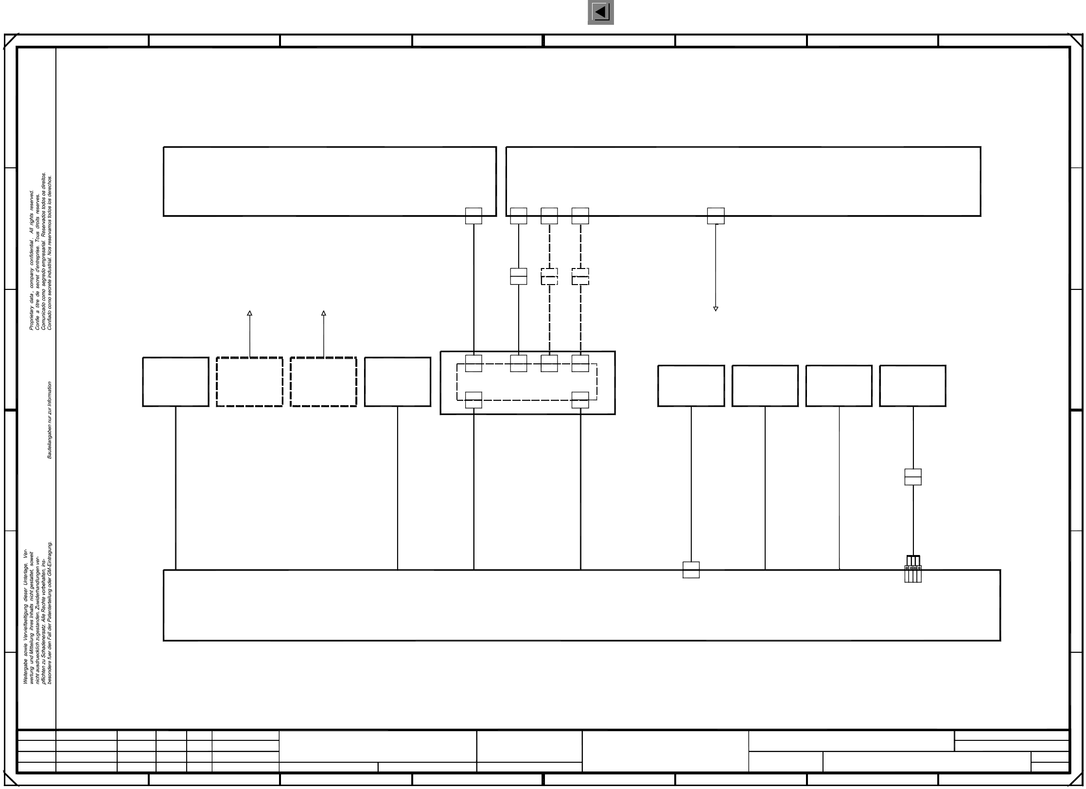
00117251-010101LD3 SIPLACE F5 basic module (Sh. 4 of 4)
Creat. byCreat. f.Orig.Status Stand.DateModified Name
Author
Check.
Date
=
SIEMENS AG
+
2345678
1
E
F F
E
D
C
B
A
00321778-xx (F4) 00329285-xx
X5‘
X5‘
00321507-xx (S4) (Option)
00321505-xx (S2) (Option)
PCB conveyor
00321512-xx
F4-6 servo unit
F5 control unit
00334638
00341851
8
C
D
A
1
765432
B
X2sf
X2sf
X14
X14
00321501-xx (S4/F4) 00329283-xx
Y652-W100317876-xx
00320777-xx
00325581-xx
X1
X1
X3
X3
X4
X4
X5
X5
X3‘
X3‘
X12
X12
X13
X13
X4sg
X4sg
00321780-xx (F4) 00329284-xx
X4‘
X4‘
X2sg
X2sg
Compressed air sensor
righth. side
lefth. side)
Terminal panel
Spare
Hood switch
Input conveyor
00303614-xx
00305815-xx
Hood switch
To preceding
00321421-xx00303617-xx
00305818-xx
station
Hood switch
Output conveyor
Option
Hood switch
To succeeding
00321421-xx
station
Option
00321579-xx
To preceding
station
00321580-xx
To succeeding
station
Conversion board
X34a
X34a
00321575-xx
X2kc 2
X2kc 3
X2kc -
gn
ye
br
X2kc 1
wh
Lamp, ready status
GND
Lamp, right main fault indicator
Lamp, left main fault indicator
00321509-xx
Lamp
Protection
(Hood switch
00321417-xx
00321574-xx
Voltage/signal
Protection
(Hood switch
00321416-xx
00321573-xx
Voltage/signal
Pneumatic system
00300912-xx
00322356-xx
01.
01.
01.
Tek
Tek
Tek
4
4
Terminal panel, lefthand side
X2kd
X2kd
X4sg
X4sg
Main fault
00321479-xx
indicator
00318689-xx
PL EA1 E2
00117251-010101LD3
SIPLACE 80 F5 basic module
#
Tekin
05.11.98
05.11.98
05.11.98
05.11.98
Function status
Product status
Document status
SMD Placement System SIPLACE 80 F5
Sheet
Sh.
2 Circuit Diagrams 52
I
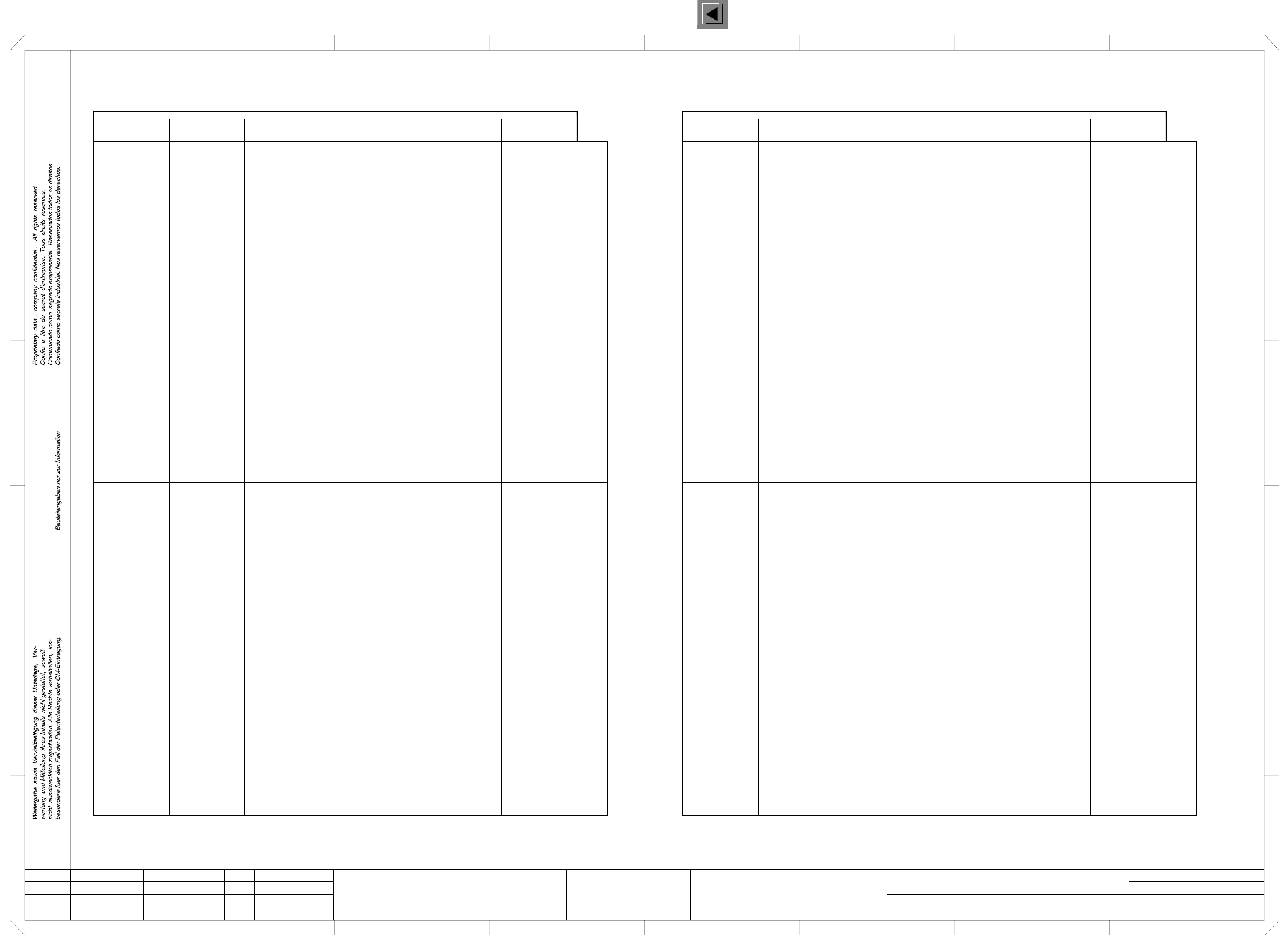
00117251-010101FD3 SIPLACE F5 basic module, input/output assignment (Sh. 1 of 2)
=
SIEMENS AG
+
PL EA1 E2
C
B
A
23
FF
E
D
67
451 67
B
C
D
E
8
12
X2sf: 1-4
X2sf: 7
X2sf: 8
X2sf: 5
X2sf: 6
Address
Port A3.2
Port A3.3
Port A3.1
Port A3.0
Port A3.7
Port A3.6
Port A3.5
Port A4.1
Port A4.0
Output
Port A4.7
Port A4.6
Port A4.5
Port A4.4
Port A4.3
Port A4.2
Output
Port A3.4
Signal designation
+30VDC switched
Motor, spare, on slow
Motor, spare, on fast
Conversion
board,
X2sf: 6
X2sf: 5
X2sf: 8
X2sf: 7
X2sf: 1-4
Plug design. I/O terminal
GND
+30VDC switched
GND
+24VDC
Motor, width adjustment wider, conveyor 1
Motor, width adjustment fast, conveyor 1
Component counter
A4/X3kg:15
A4/X3kg:14
A4/X5kg:G
X2sf:11
X2sf:10
X2sf:12
X3sf: 6
X3sf: 5
X3sf: 1-4
X2sf:13-14
A4/X4kg:18
A4/X5kg:5
A4/X5kg:6
A4/X5kg:7
A3/X2kf:P
A4/X5kg:8
A4/X5kg:M
X3sf: 8
X3sf: 9
X3sf:11
X3sf:10
X3sf:12
X4sf: 1-4(*)
X3sf:13-14
X3sf: 7 A4/X4kg:19
X2sf: 9
PCB handling
Motor, center conveyor on slow, conveyor 1
Motor, center conveyor on fast, conveyor 1
Motor, PCB input conveyor on fast, conveyor 1
Motor, output conveyor on fast, conveyor 1
Motor, output conveyor on slow 2, conveyor 1
Motor, output conveyor on slow 1, conveyor 1
’Received’ to previous station from conveyor 1
’Permission’ to previous station from conveyor 1
Motor, width adjustment narrower, conveyor 1
’Transferred’ to following station from conveyor 1
’Request’ to following station from conveyor 1
Input
Port E3.4
Port E3.6
Port E3.7
Port E3.5
Port E3.3
Port E3.2
Port E3.1
Port E3.0
Input
Port E4.4
Port E4.6
Port E4.5
Port E4.3
Port E4.2
Port E4.1
Port E4.0
Port E4.7
Distance sensor
Crash, portal 1
GND
Bero, nozzle changer SP, portal 2 opened
Bero, nozzle changer SP, portal 1 opened
Bero, nozzle changer SP, portal 1 closed
Bero, nozzle changer SP, portal 2 closed
+24VDC
A3/X2kf:1
A3/X2kf:2
A3/X2kf:3
A3/X2kf:4
A3/X2kf:6
A3/X2kf:7
A3/X2kf:8
A3/X2kf:M
A3/X2kf:5
X4sf: 6
X4sf: 5
X4sf: 8
X4sf: 7
X4sf:10
X4sf:12
X4sf:11
X4sf: 9
X4sf:13-14
A4/X3kg:19
A4/X3kg:18
A4/X5kg:P
A4/X4kg:14
A4/X6kg:5
A4/X6kg:6
A4/X6kg:7
A4/X4kg:15
X5sf: 6
X5sf: 5
X5sf: 8
X5sf: 7
X5sf:10
X5sf:11
X5sf: 9
X5sf: 1-4(*)
GND
A4/X6kg:8
A4/X5kg:M
X5sf:12
X5sf:13-14
Pins marked with an ’*’ are not hard-wired !
Ultrasonic sensor, input conveyor, conveyor 2
Ultrasonic sensor, input conveyor, conveyor 1
Ultrasonic sensor, output conveyor, transport 1
Ultrasonic sensor, output conveyor, transport 2
’Request’ to conveyor 1 from previous station
’Transferred’ to conveyor 1 from previous station
’Permission’ to conveyor 1 from following station
’Received’ to conveyor 1 from following station
Ultrasonic sensor, center conveyor, conveyor 2
Ultrasonic sensor, center conveyor, conveyor 1
Address
Port A1.2
Port A1.3
Port A1.0
Port A1.1
Signal designation
+24VDC
Retract lifting table, PCB release, conveyor 1
Extend lifting table, PCB clamping, conveyor 1
Valve, nozzle changer 2 opened
Valve, nozzle changer 1 opened
Port A1.7
Port A1.5
Port A1.6
Port A2.1
Port A2.0
Output
Port A2.7
Port A2.6
Port A2.5
Port A2.4
Port A2.3
Port A2.2
GND
+24VDC
Valve, ceramic substrate centering, conveyor 1
Valve, extend stopper 2, conveyor 2
Lamp, main fault indicator ready (green)
Valve, extend stopper 1, conveyor 1
Icos MC1
MC1 (M44)
GND
+24VDC
Software release, control on
Lamp, main fault indicator lefthand side (white)
Command ’read PCB barcode’ 2 (contactor relay)
Command ’read PCB barcode’ 1 (contactor relay)
Lamp, main fault indicator righthand side (white)
Output
Compressed air on/off Port A1.4
I/O terminal
A1/X2ka:P
A1/X2ka:1
A1/X2ka:2
A1/X2ka:3
A1/X2ka:4
X2se: 1-4
X2se: 6
X2se: 5
X2se: 8
X2se: 7
Plug design.
A1/X2ka:6
A1/X2ka:7
A1/X2ka:8
A1/X2ka:M
A2/X2kc:2
A2/X2kc:1
A2/X2kc:P
X2se:11
X2se:10
X2se:12
X3se: 1-4
X3se: 6
X3se: 5
X2se:13-14
A2/X2kc:7
A2/X2kc:6
A2/X2kc:5
A2/X2kc:4
A2/X2kc:8
A2/X2kc:M
A1/X2kb:P
X3se: 8
X3se: 9
X3se:11
X3se:10
X3se:12
X4se: 1-4(*)
X3se:13-14
A2/X2kc:3X3se: 7
A1/X2ka:5X2se: 9
Input
Port E1.4
Port E1.6
Port E1.7
Port E1.5
Port E1.2
Port E1.3
Port E1.0
Port E1.1
Input
Port E2.4
Port E2.6
Port E2.5
Port E2.3
Port E2.2
Port E2.1
Port E2.0
GND
Limit switch, width adjustment, conveyor 1
Bero, stopper 1 retracted, conveyor 1
Bero, stopper 2 retracted, conveyor 2
Bero, position width adjustment, conveyor 1
Bero, lifting table bottom position, conveyor 1
Bero, lifting table top position, conveyor 1
Bero, ceramic substrate centering, conveyor 1
Contactor monitoring (software release)
+24VDC
Key-operated switch, 0 -> actuated
EMERG.-STOP button, 1 -> actuated
’Off’ button, 0 -> actuated
Control on, 1 -> K3/K4 on
Protective cover, 1 -> opened
’On’ button, 1 -> actuated
Compressed air sensor, 1 -> compressed air available
Port E2.7
GND
Control on, 1 -> K1/K2 on
A1/X2kb:1
A1/X2kb:2
A1/X2kb:3
A1/X2kb:4
A1/X2kb:6
A1/X2kb:7
A1/X2kb:8
A1/X2kb:M
A1/X2kb:5
X4se: 6
X4se: 5
X4se: 8
X4se: 7
X4se:10
X4se:12
X4se:11
X4se: 9
X4se:13-14
A2/X2kd:2
A2/X2kd:1
A2/X2kd:P
A2/X2kd:7
345
Tek
Tek
Tek
01.
01.
01.
17.07.98
17.07.98
17.07.98
17.07.1998
Tekin
00117251-010101FD3
8
A
1
2
SMD-Placement System SIPLACE 80 F5
Product status
Doc. status
Function status
I/O assignment
SIPLACE 80 F5, basic module
X5se:13-14
X5se:12
A2/X2kd:M
A2/X2kd:8
X5se: 1-4(*)
X5se: 9
X5se:11
X5se:10
X5se: 7
X5se: 8
X5se: 5
X5se: 6
A2/X2kd:3
A2/X2kd:4
A2/X2kd:5
A2/X2kd:6
A2/X2kd:7
A2/X2kd:P
A2/X2kd:1
A2/X2kd:2
X4se:13-14
X4se: 9
X4se:11
X4se:12
X4se:10
X4se: 7
X4se: 8
X4se: 5
X4se: 6
A1/X2kb:5
A1/X2kb:M
A1/X2kb:8
A1/X2kb:7
A1/X2kb:6
A1/X2kb:4
A1/X2kb:3
A1/X2kb:2
A1/X2kb:1
GND
+24VDC
GND
X2se: 9 A1/X2ka:5
X3se: 7 A2/X2kc:3
X3se:13-14
X4se: 1-4(*)
X3se:12
X3se:10
X3se:11
X3se: 9
X3se: 8
A1/X2kb:P
A2/X2kc:M
A2/X2kc:8
A2/X2kc:4
A2/X2kc:5
A2/X2kc:6
A2/X2kc:7
X2se:13-14
X3se: 5
X3se: 6
X3se: 1-4
X2se:12
X2se:10
X2se:11
A2/X2kc:P
A2/X2kc:1
A2/X2kc:2
A1/X2ka:M
A1/X2ka:8
A1/X2ka:7
A1/X2ka:6
X2se: 7
X2se: 8
X2se: 5
X2se: 6
X2se: 1-4
A1/X2ka:4
A1/X2ka:3
A1/X2ka:2
A1/X2ka:1
A1/X2ka:P
+24VDC
GND
MC1 (M44)
Icos MC1
+24VDC
GND
+24VDC
X5sf:13-14
X5sf:12
A4/X5kg:M
A4/X6kg:8
GND
X5sf: 1-4(*)
X5sf: 9
X5sf:11
X5sf:10
X5sf: 7
X5sf: 8
X5sf: 5
X5sf: 6
A4/X4kg:15
A4/X6kg:7
A4/X6kg:6
A4/X6kg:5
A4/X4kg:14
A4/X5kg:P
A4/X3kg:18
A4/X3kg:19
X4sf:13-14
X4sf: 9
X4sf:11
X4sf:12
X4sf:10
X4sf: 7
X4sf: 8
X4sf: 5
X4sf: 6
A3/X2kf:5
A3/X2kf:M
A3/X2kf:8
A3/X2kf:7
A3/X2kf:6
A3/X2kf:4
A3/X2kf:3
A3/X2kf:2
A3/X2kf:1
+24VDC
GND
X2sf: 9
A4/X4kg:19X3sf: 7
X3sf:13-14
X4sf: 1-4(*)
X3sf:12
X3sf:10
X3sf:11
X3sf: 9
X3sf: 8
A4/X5kg:M
A4/X5kg:8
A3/X2kf:P
A4/X5kg:7
A4/X5kg:6
A4/X5kg:5
A4/X4kg:18
X2sf:13-14
X3sf: 1-4
X3sf: 5
X3sf: 6
X2sf:12
X2sf:10
X2sf:11
A4/X5kg:G
A4/X3kg:14
A4/X3kg:15
+24VDC
GND
GND
A2/X2kd:6
A2/X2kd:5
A2/X2kd:4
A2/X2kd:3
X5se: 6
X5se: 5
X5se: 8
X5se: 7
X5se:10
X5se:11
X5se: 9
X5se: 1-4(*)
A2/X2kd:8
A2/X2kd:M
X5se:12
X5se:13-14
Pins marked with an ’*’ are not hard-wired !
Sheet
Sh.
Status DateModified Name Stand. Orig. Creat. f. Creat. by
Author
Date
Check.