Detailed Circuit Diagram Folder SIPLACE F5.pdf - 第80页
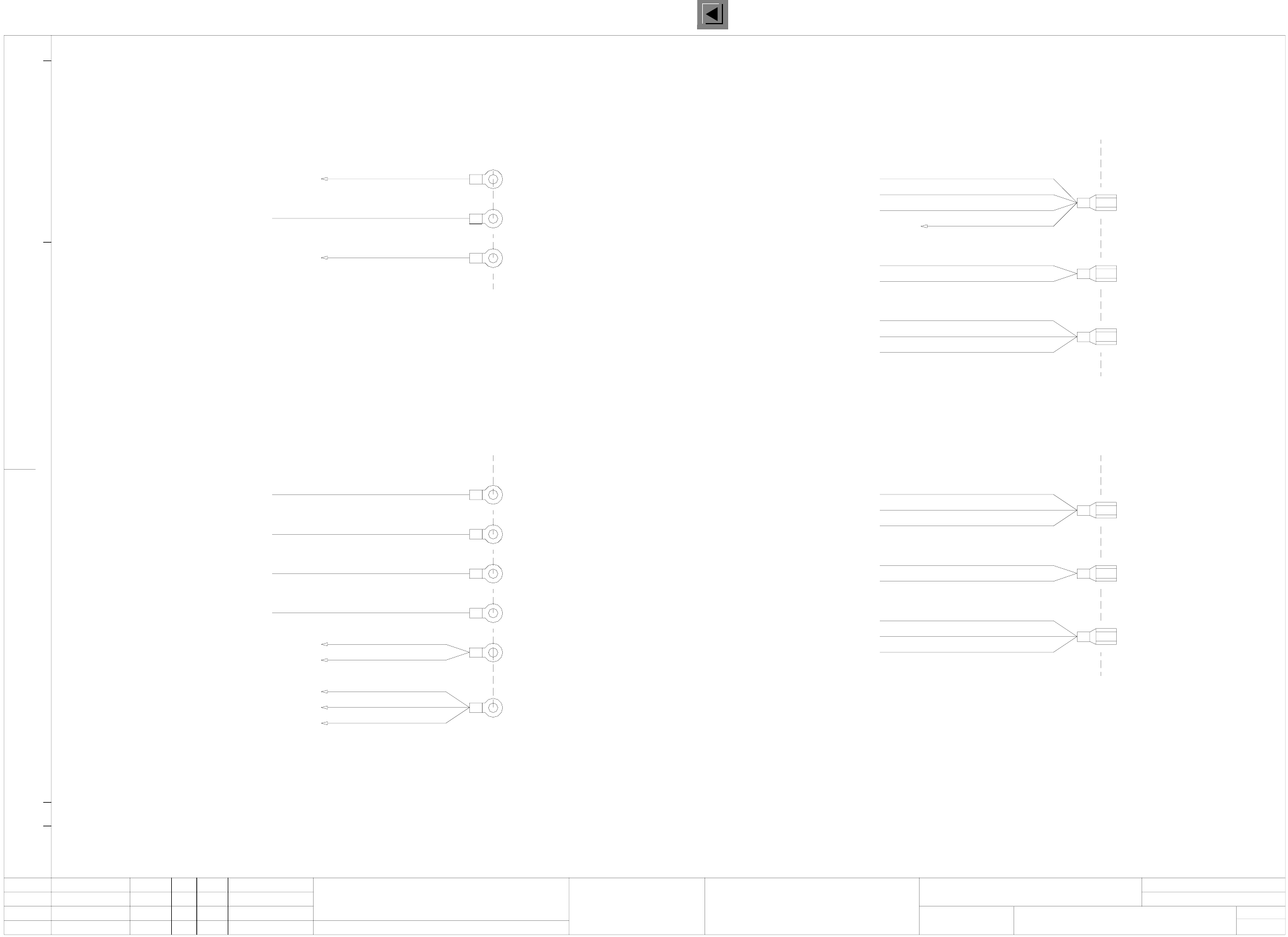
2 Circuit Diagr ams 80 I 0033464 7-010 101 TD3 F5 servo unit, ba sic modu le (pi n assign ment) (S h. 1 o f 3) Servo unit 80F4 / 6 17.06.199 7 Tekin 0033464 7-01 334647T 1 1. 16. 09. 97 1. Tek 1. 16. 09. 97 16. 09. 97 Te…
2 Circuit Diagrams 79
I
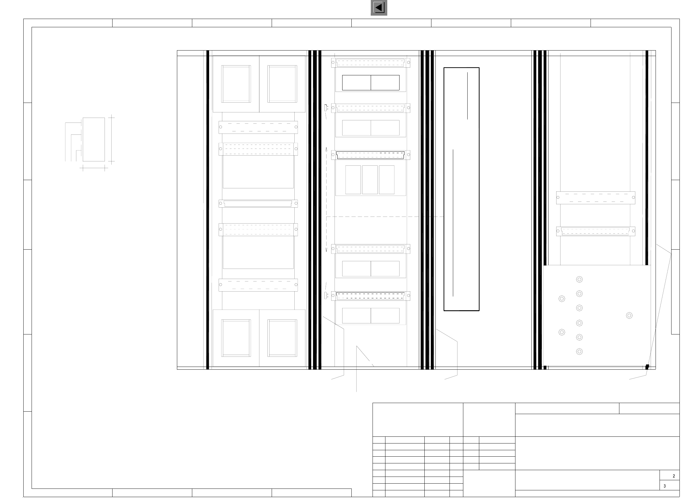
00334647-010101LD3 F5 servo unit, basic module, power supply (Sh. 3 of 3)
1.
1. Tek
16.09.97
1.
16.09.97
16.09.97
Tek
Tek
16.09.1997
Tekin
00334647-01
334647L1
Base
Servo unit 80F4 / 6
00334647-010101LD3
vi / 1.5mm²
X2:4From plug
From plug
From plug
X2:5
X2:3
vi / 1.5mm²
vi / 1.5mm²
From plug
From plug X2:2
X2:1
vi / 1.5mm²
vi / 1.5mm²
2L+
X14:3
pkbk / 0.25mm²
pkbk / 0.25mm²
pkbk / 0.25mm²
X4vk:1
X4vf:1
X4vd:1
Backplane, Z-axis, IC A19
Backplane, Z-axis, SP A16
Backplane, DP1-axis, A15
Backplane, Z-axis, IC A19
Backplane, Z-axis, SP A16
Backplane, DP1-axis, A15
X4vf:2 pkgr / 0.25mm²
pkgr / 0.25mm²X4vk:2
X4vd:2 pkgr / 0.25mm²
pkbk / 0.25mm²
X14:7
pk / 1.5mm²
X2:6From plug
pk / 1.0mm²
To plug
X7va:3 vi / 1.5mm²
Backplane, X-axis, A13
X7vb:3 vi / 1.5mm²
vi / 0.25mm²
X13:c2 vi / 1.0mm²
Sheet
Sh.
Mat-Nr.:
Upkpr./Epk.f./Epk.d.
Date
Author
Check.
Stand.NameDateModifiedStatus
Ballast circuit A11
Measurement socket MB9
Backplane, Y-axis, A14
Backplane, star A17
Backplane, DR-axis, A18
Backplane, Y-axis, A14
Backplane, X-axis, A13
Anti-crash board A10
Backplane, Y-axis, A14
Backplane, X-axis, A13
Anti-crash board A10
To plug
Backplane, star A17
Backplane, DR-axis, A18
Measurement socket MB8
pk / 0.25mm²
(Power supply)
X4vg:1
X4vc:1 pkbk / 0.25mm²
pkbk / 0.25mm²
X11g:1
X6vb:2
X6va:2
pkbk / 0.25mm²
pkbk / 0.25mm²
pkbk / 0.25mm²
Power supply unit
+15V
X4vc:2 pkgr / 0.25mm²
X11g:5
X6vb:1
X6va:1
pkgr / 0.25mm²
pkgr / 0.25mm²
pkgr / 0.25mm²
Power supply unit
-15V
pkgr / 0.25mm²X4vg:2
Star point 008
1L+/5L+
Star point 009
Pin 4
Pin 8
Pin 12
Pin 18
Pin 22
Pin 26
AUT5-BSM
Siemens AG
Stromlaufplan/Circuit diagram
19181716151413121110987654321
Siemens AG
19181716151413121110987654321
Function status
Product status
Doc. status
SMD Placement System Siplace 80F4
3
3
6-nozzle revolver head
2 Circuit Diagrams 80
I
00334647-010101TD3 F5 servo unit, basic module (pin assignment) (Sh. 1 of 3)
Servo unit 80F4 / 6
17.06.1997
Tekin
00334647-01
334647T1
1.
16.09.97
1.
Tek
1.
16.09.97
16.09.97
Tek
Tek
00334647-010101TD3
+24V
1L-
1L-
+5V
6L+
7L+
2L+/5L+
6L+
7L+
2L+
1L+
1L+
1L+
1L+
2L+7L+
*
*
*
*
*
*
Socket contacts 0.5-2.1mm²
Socket contacts 0.5-2.1mm²
Pin contacts 0.5-2.1mm²
Socket contacts 0.5-2.1mm²
Pin contacts 0.5-2.1mm²
Pins 4-6 socket contacts 0.5-2.1mm²
Pins 1-3 pin contacts 0.5-2.1mm²
Pin designation*
X2
X3
X4
X5
X6
X14
1
2
3
6
8
7
4
9
+5V
+24V 6L++15V
X14
X2
1L+
1L-
+12V
1L-
X3
X4
M-
M+
T+
T-
X5
T-M-
T+M+
M-M+
X6
have to be pinched out.
All pins marked with a cross
Note!
(Pin assignment)
Siemens AG
1
1
243
2345678
A
B
C
D
E
F
A
B
C
D
AUT5-BSM
1 4
5
2
3 6
1 4
5
2
3 6
1 4
5
2
3 6
1 4
5
2
3 6
1 4
5
2
3 6
JP1
12
13
14
15
16
17
18
19
20
21
22
23
24
25
26
27
28
29
30
32
31
11
10
9
8
7
6
5
4
3
2
1
Pin ab
21
Anti-crash board
56
56
21
56
21
65
21
12
910
12
910
12
56
key
n.c. n.c.
Axis Enable (+15V)
Axis Enable (+15V)
Tacho+
Tacho+
key
key
Axis Enable
Axis Enable
Tacho-
Tacho-
n.c.
n.c.key
key
+5V
n.c.
Meldung "Crash" an S5 ->
n.c.
n.c.
n.c.
n.c.
Axis Enable (+15V)
Tacho+
n.c.
n.c.
Axis Enable (+15V)
Tacho+
-15V
+15V
n.c.
Distance sensor
Anti-crash prox. switch 2 Y-axis
Anti-crash prox. switch 1 Y-axis
Anti-crash prox. switch 2 X-axis
n.c.
n.c.
n.c.
Axis Enable
Tacho-
n.c.
key
Axis Enable
Tacho-
Anti-crash prox. switch 1 X-axis
T
T
Distance sensor
n.c.n.c.
Anti-crash prox. switch 1 X-axis
Anti-crash prox. switch 2 X-axis
Anti-crash prox. switch 1 Y-axis
Anti-crash prox. switch 2 Y-axis
Distance sensor
key
n.c.
"Crash" signal to S5 ->
T
T
Distance sensor
T
+24V
a
b
c
d
e
f
g
SMD-Placement System Siplace 80F4
Product status
Doc. status
Function status
6-nozzle revolver head
Sheet
Sh.
Status Modified Date Name
CAD-Datei:
Mat-Nr.:
Date
Author
Check.
Stand.
Scale
2 Circuit Diagrams 81
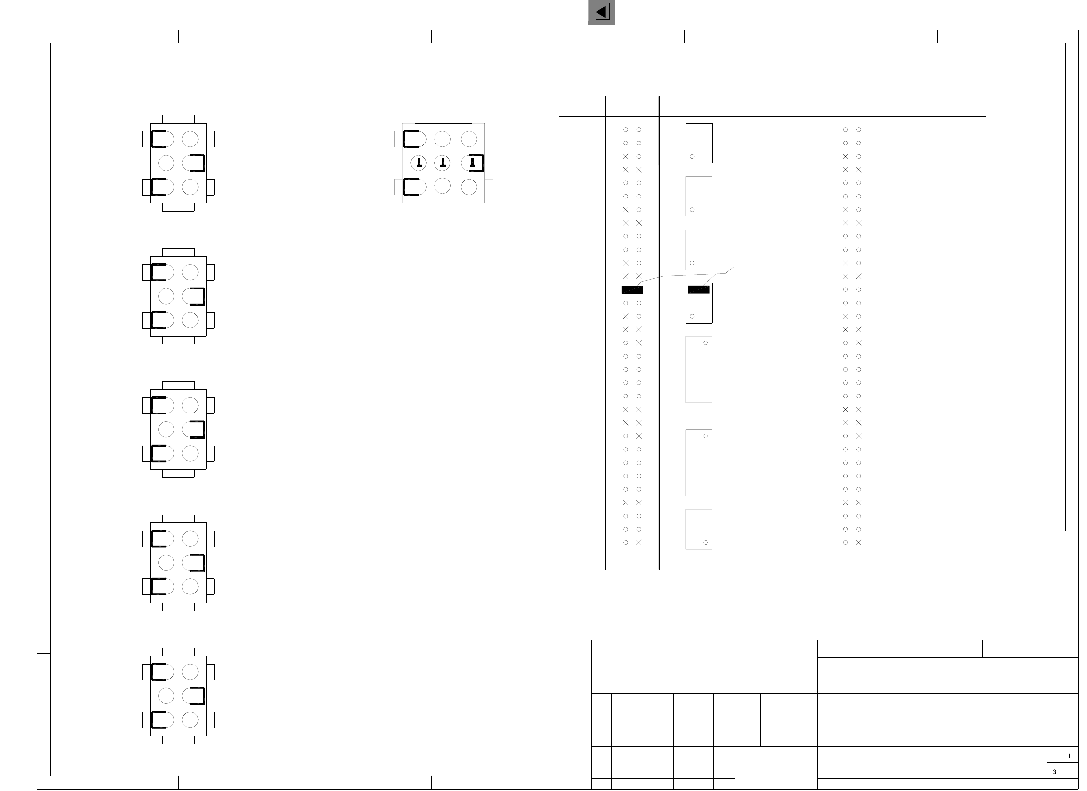
I
00334647-010101TD3 F5 servo unit, basic module (viewed from the front) (Sh. 2 of 3)
Part 006Part 005
Servo unit 80F4 / 6 base
17.06.1997
Tekin
00334647-01
334647T1
1.
16.09.97
1.
Tek
1.
16.09.97
16.09.97
Tek
Tek
00334647-010101TD3
2L+/5L+2L+
7L+
2L+/5L+
DP1-axis, SP head, "A15"
Dynamic brake, X
X-axis, "A13"
Y-axis, "A14"
Anti-crash board X11
Dynamic brake, Y
X7
X8
Ballast circuit
Z-axis, IC head, "A19"
DR-axis, IC head, "A18"
Stern SP head, "A17"
Z-axis, SP head, "A16"
A: Identification label, assembly inscription according to recommendation VA-F-510-001
(flush with the front plate):
Apply the following labels inside
* Note
B: Inspection label, identification: testing eng., year, month
Manufacturer/location of plant according to SN 37040
Date (year/month/day) according to SN 01007
Numeral
Prepare the labeling tapes A-C
acc. to material no. 323329
and fit them.
Inscription
tape C
* Note
Inscription
tape B
Inscription
tape A
"A20"
Sheet
Sh.
CAD-Datei:
Mat-Nr.:
Status Modified Date Name
Stand.
Check.
Author
Date
Scale
Contact springs are inserted in parts 005 and 006 of the guide rails.
The contact springs are to be inserted only on the front side and only in the
bottom rail of the SP-head and IC-head Z servos.
Note !
SMD-Placement System Siplace 80F4
Product status
Doc. status
Function status
6-nozzle revolver head
Power supply unit
X12
X13
1:2
(viewed from the front)
007
GND
6L+ 24V 12V 5V
009008
005005004003002001
L2
L1
L4
L3
Fan unit
18
40
00334647 / 01
AA-BBBB-CCCC
SIEMENS AUT 5
Siemens AG
1
1
243
2345678
A
B
C
D
E
F
A
B
C
D
AUT5-BSM