Detailed Circuit Diagram Folder SIPLACE F5.pdf - 第55页
2 Circuit Diagr ams 55 I 0032108 6-050 101FD3 S afety conce pt over view (safe ty circui t) (Sh . 2 of 3 ) AUT 5 SIEMENS Safety ci rcui t 01. 01. 05. c095 2f41_d Leh 23.01 .98 H1: LED MAIN Leh Leh 23.0 1.98 23.01 .98 1 2…
2 Circuit Diagrams 54
I
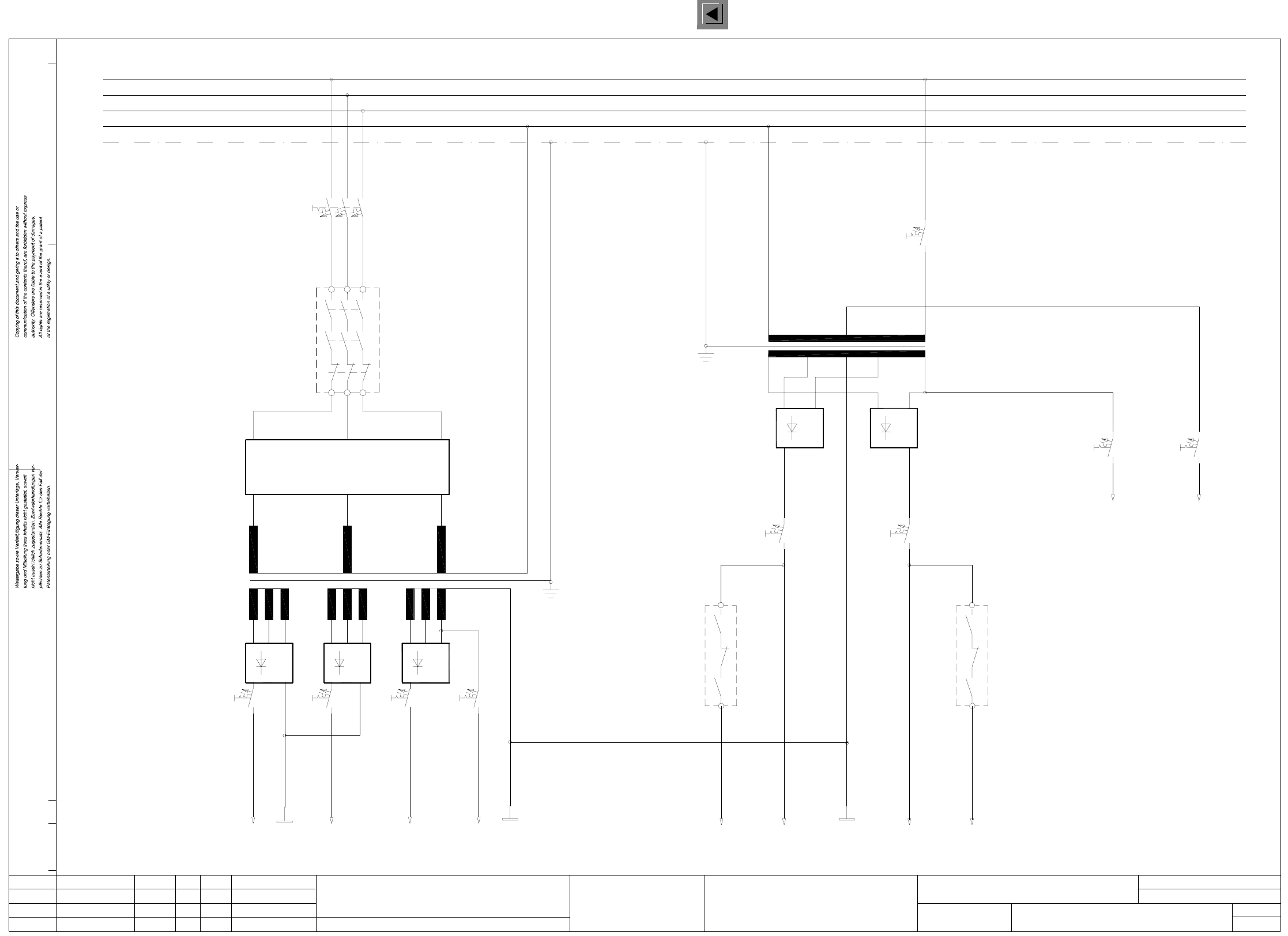
00321086-050101FD3 Circuit diagram overview, safety concept (power unit) (Sh. 1 of 3)
Stromlaufplan/Circuit diagram
(power unit)
Safety concept
Circuit diagram overview
01.
01.
05.
c0952f41_d
23.01.98
Leh
AUT 5
00321086-04
1L+
1L-
3L+2L+
23.01.98
Leh
23.01.98
Leh
Tuth
21.07.98
12345
(x, y axes)
(star/lifting table)
(tape cutter)
4L+
2L-
67
(ext. WPC)
8
SIEMENS
910
switched
24VAC
(x, y slow)
V3
F4 F5 F6
V1 V2
F7
T2
00321086-050101FD3
7L+6L+
2L-
5L+
11 12 13
switched
14 15
(star slow)
(dp1/Z axes)
(Lifting table)
1816 17
K2
F9F8
control unit
To
150VAC
safety circuit
24VAC
To
F2
current limiter
Inrush
A1
K1
L1
L2
L3
PE
N
T1
V5
F10 F11
F3
PE
L3
N
L2
L1
V4
13
14
K2
23
24
Function status
Product status
Doc. status
SMD Placement System Siplace 80S20/F4
1
3Status Modified Orig./Creat. f./Creat.by
Date
Author
Check.
Stand.NameDate
Mat. no.:
CAD file:
Sh.
Sh.
2 Circuit Diagrams 55
I
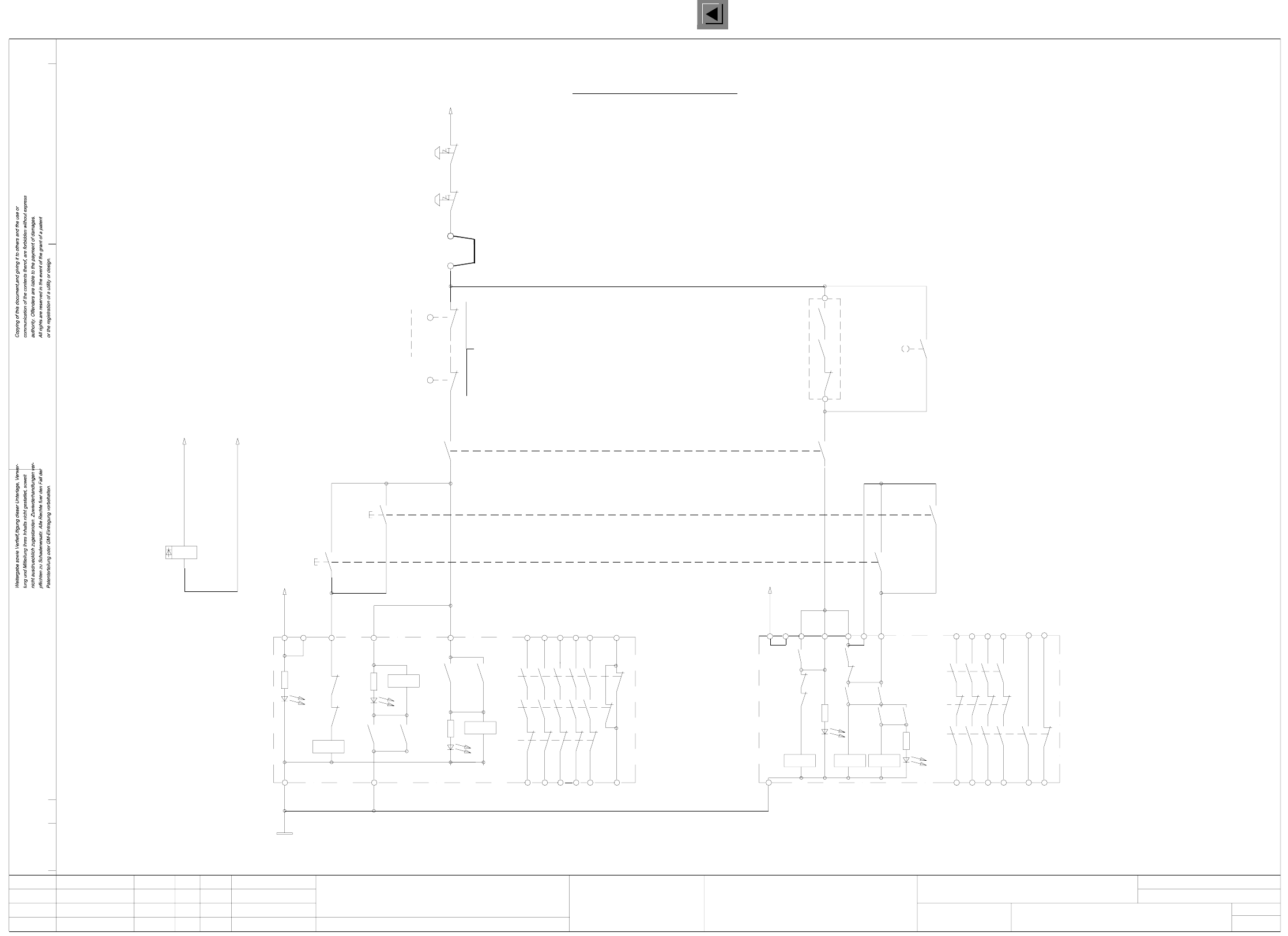
00321086-050101FD3 Safety concept overview (safety circuit) (Sh. 2 of 3)
AUT 5
SIEMENS
Safety circuit
01.
01.
05.
c0952f41_d
Leh
23.01.98
H1: LED MAIN
Leh
Leh
23.01.98
23.01.98
1
21.07.98
Tuth
234
H2+H3 = release
00321086-04
56789
H2: LED channel 2H3: LED channel 1
3414
24
44
54
66
X4
K1 3TK2805-0AC2
K1’
K2’
H1
K3’
K2’K2’
K1’ K3’
H2
H3
K1’
K2’
K3’
K1’ K2’
K1
K3’
65
Y0906-S2
Y0907-S2
C0952-K3
Software release
for machine ON
C0952-K3
Cover switches
Y0438-S1
(1-n)
Y0413-S1
Connection for external
safety loops
X211
X211
Y0906-S1
EMERG.-STOP button
EMERG.-STOP button
(input)
(output)
Y0907-S1
~24VAC
Stromlaufplan/Circuit diagram
00321086-050101FD3
14
H1’: LED release
Safety concept overview
(safety circuit)
10 11 12 13
H2’: LED ready
H1’
15 16 17 18
K2 3TK2804-0AC2
K3’
K2’
H2’
K3’
K1’ K3’
K1’
K2’
K1’
L1 X1
K1’
K1’
K2’
K3’
X5
K3’
X3X2 X4
44
43
54
53
Key-operated switch
Y0907-S4
K1
6557433323
13
X6
24V AC
24
14 34 44
58 66
L2
K1’ K2’
(ON button)
(output)
(input)
5343
3323
13
X5X3
24V AC
X6
L2
X1L1
Function status
Product status
Doc. status
SMD Placement System Siplace 80S20/F4
2
3
POWER SUPPLY
UNIT
Status Modified Date Name Stand.
Check.
Author
Date
Mat. no.:
CAD file:
Orig./Creat. f./Creat.by
Sh.
Sh.
2 Circuit Diagrams 56
I
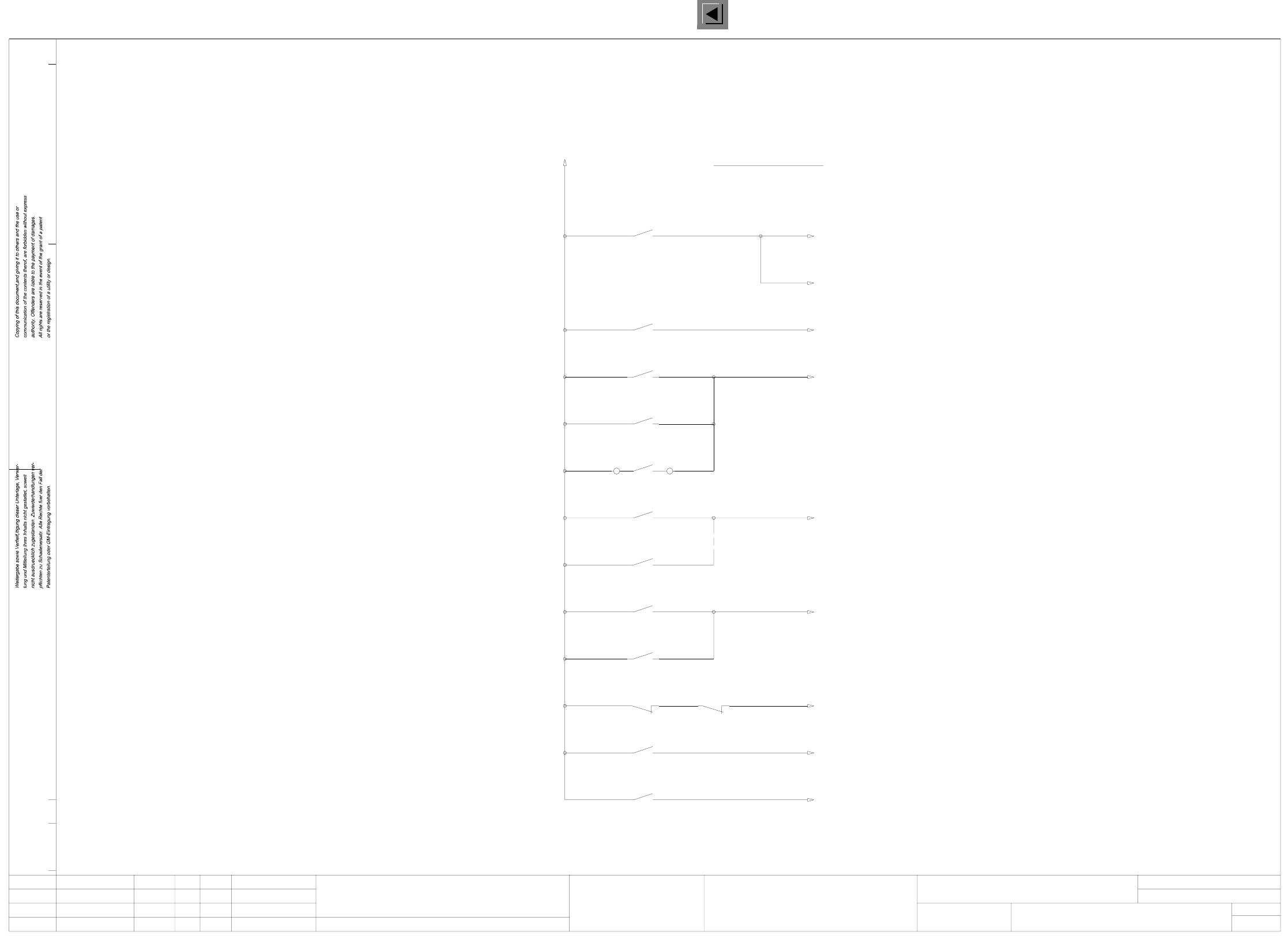
00321086-050101FD3 Safety concept overview (signaling circuit) (Sh. 3 of 3)
c0952f41_d
01.
23.01.98
Leh
21.07.98
Tuth
01.
05.
23.01.98
23.01.98
Leh
Leh
12 435
00321086-04
67
Software release
Key-operated switch
Input/output
Output
Input
Cover switches
(1-n)
Cover switches
AUT 5
Stromlaufplan/Circuit diagram
00321086-050101FD3
Monitoring
software release
SIEMENS
8910
Safety concept overview
(signaling circuit)
11 12
C0952-K3
1513 14 16 17 18
OFF button
Monitoring
Monitoring
key-operated switch
Y0907-S4
Y0907-S3Y0906-S3
Y0907-S2
ON button
Monitoring
Monitoring
cover switches
Y0906-S2
Y0438-S1
Y0413-S1
+24VDC
external
Output
Input
Control ON
Control ON
Monitoring
EMERG.-STOP button
X210
Y0907-S1
Y0906-S1
(SIPLACE 80F)
Monitoring
Monitoring
C0952-K2
C0952-K1
K2
Laser
K1
Signaling circuit
l
Function status
Product status
Doc. status
SMD Placement System Siplace 80S20/F4
3
3Status Modified Date Name Stand.
Check.
Author
Date
Mat. no.:
CAD file:
Orig./Creat. f./Creat.by
Sh.
Sh.